Fuel gas treatment device

A fuel gas and processing device technology, which is applied in the directions of fuel injection control, electrical control, engine components, etc., can solve the problems that fuel gas is difficult to dissolve into engine oil, the system is complicated, and the number of parts is increased, so as to reduce the number of parts and reduce the number of parts. Design changes, the effect of efficient absorption

Active Publication Date: 2013-03-20
HONDA MOTOR CO LTD
View PDF5 Cites 0 Cited by
  • Summary
  • Abstract
  • Description
  • Claims
  • Application Information

AI Technical Summary

Problems solved by technology

[0006] However, in the fuel gas treatment device described in Patent Document 1, the opening of the evaporated fuel treatment pipe is only arranged in the engine oil in the oil pan and the fuel gas is discharged into the engine oil. When the fuel gas discharge destination is a static region where the operation of the engine oil is relatively stable, there is a possibility that the fuel gas is difficult to dissolve into the engine oil, and a pump for forcibly transporting the fuel gas, etc. is required, and the number of parts increases. , the system becomes complex

Method used


Image

  • Fuel gas treatment device
  • Fuel gas treatment device
  • Fuel gas treatment device

Examples


Embodiment Construction

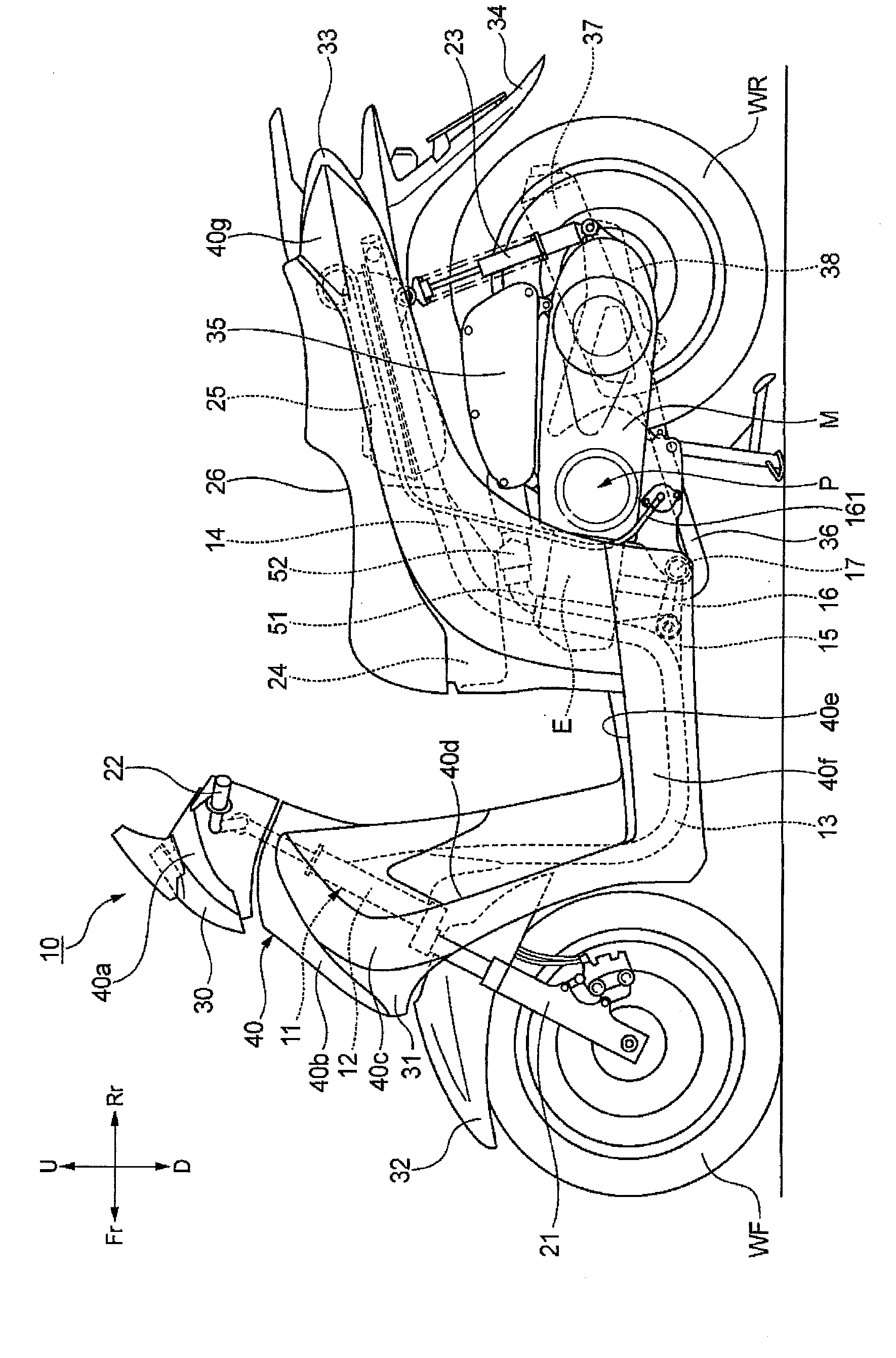
[0049] Hereinafter, an embodiment of the fuel gas processing device of the present invention will be described in detail with reference to the drawings. In addition, the drawings are viewed in the direction of the symbols. In the following description, front and rear, left and right, and up and down are in accordance with the directions seen from the operator. In the drawings, the front of the vehicle is represented by Fr, the rear by Rr, and the left side It is represented by L, the right side is represented by R, the top is represented by U, and the bottom is represented by D.

[0050] The two-wheeled motor vehicle 10 of the present embodiment is a scooter type vehicle, such as figure 1 As shown, the vehicle frame 11 is composed of the following parts: a head pipe 12, which is arranged at the front end; a main frame 13, which extends downward from the head pipe 12 and extends backward; a pair of left and right rear frames 14, which extend from the rear of the main frame 13 ...


PUM


Abstract

Provided is a fuel gas treatment device, which discharges fuel gas to a dynamic region of engine oil without a pump used for transporting the fuel gas, thereby enabling the fuel gas to dissolve in the engine oil. Fuel gas generated in a fuel tank (25) is guided into a crankcase (41) of an engine (E) from an opening part (173) of a fuel gas intake pipe (161) through a fuel gas intake pipe (161), and is accumulated in the engine oil inside the crankcase (41), in operation of the engine (E), the fuel gas is guided into an air suction pipe (51) from the engine oil through a purification passage (163), the fuel gas treatment device (160) has an oil tray (131) formed at a lower part of the crankcase (41) and used for storing engine oil, an oil suction inlet (136a) communicated with the oil tray (131) is formed at one end, an oil suction passage (136) communication with an oil pump (125) is formed at the other end, and the opening part (173) of the fuel gas intake pipe (161) is configured to be opposite to the oil suction inlet (136a).

Description

technical field [0001] The invention relates to a fuel gas processing device for a vehicle, in particular to a fuel gas processing device for a two-wheeled motor vehicle. Background technique [0002] As a conventional fuel gas treatment device, a technique is known in which fuel gas evaporated in a fuel tank is guided to an engine to prevent the fuel gas from being discharged into the atmosphere (for example, refer to Patent Document 1). In this fuel gas processing device, the tip of the evaporated fuel processing piping that leads out the fuel gas passes through an oil pan and is placed in the engine oil in the oil pan so that the fuel gas is discharged from the opening formed at the tip. The part is discharged into the engine oil, so that the fuel gas dissolves into the engine oil. [0003] (Prior art literature) [0004] (patent documents) [0005] Patent Document 1: Japanese Patent Laid-Open No. 2005-061305 [0006] However, in the fuel gas treatment device describe...

Claims


Application Information

Patent Timeline
Patent Type & Authority Applications(China)
IPC IPC(8): F01M13/00F01M13/04F02D13/02F02D41/02F02D45/00
Inventor 井元丰土屋粒二森本泰弘
Owner HONDA MOTOR CO LTD
Why Eureka
Try Eureka