Bi-energy pneumatic submersible pump for mine

A submersible pump and dual-power technology, which is applied in the field of dual-power mine pneumatic submersible pumps, can solve the problems of complex operating conditions, no flow regulating valve in the water discharge pipeline, and the lift cannot meet the user's requirements, etc., to achieve good adaptability, The effect of reliable assembly connection and large torque

Active Publication Date: 2013-03-20
CHANGZHOU DOUSHI PNEUMATIC MACHINERY
View PDF7 Cites 4 Cited by
  • Summary
  • Abstract
  • Description
  • Claims
  • Application Information

AI Technical Summary

Problems solved by technology

Mine pneumatic (pneumatic) pumps have a remarkable feature. Due to the portability of the pump, a pump is often used in many occasions, the operating conditions are extremely complex, and the actual operating conditions often change, including compressed air pipelines. The pressure and flow change; and there is no flow regulating valve in the water discharge pipeline, which only means that the mining air pump is operating under the condition of large flow, but most of the actual head cannot meet the user's requirements. At present, it can only solve the work of the working face. Site Drainage Requirements

Method used


Image

  • Bi-energy pneumatic submersible pump for mine
  • Bi-energy pneumatic submersible pump for mine
  • Bi-energy pneumatic submersible pump for mine

Examples


Embodiment 1

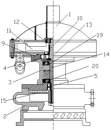
[0037] Preferred embodiment one of the present invention: the motor 1 is a turbine air motor, and the turbine air motor includes a turbine output shaft 10, a turbine 11 arranged on the turbine output shaft 10, and the turbine output shaft 10 is respectively provided with Bearing 12 on the turbine output shaft and bearing 13 under the turbine output shaft are arranged.

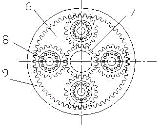
[0038] The sun gear 7 is integrally arranged on one end of the turbine output shaft 10, the water pump 2 includes a power shaft 14, the power shaft 14 is integrally arranged with the planet carrier 6, and the output end of the power shaft 14 is provided with impeller blades 15.

[0039] The turbine output shaft 10 is the input shaft of the variable speed transmission device 3, and the output shaft of the variable speed transmission device 3 is the power shaft 14 of the water pump 2. There is no coupling in the middle between the turbine output shaft 10 and the power shaft 14. The transitional flange has no asy...

Embodiment 2

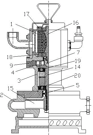
[0042] Preferred embodiment 2 of the present invention: the motor 1 is a volume vane air motor, and the volume vane air motor includes a vane rotor shaft 16, and the vane rotor shaft 16 is provided with an upper rotor shaft bearing 17 and a rotor shaft lower bearing. bearing 18.

[0043] The output end of the vane rotor shaft 16 is connected to the sun gear 7, the water pump 2 includes a power shaft 14, and the power shaft 14 is integrated with the planet carrier 6, and the output end of the power shaft 14 is provided with an impeller slice 15.

[0044] The blade type rotor shaft 16 is the input shaft of the variable speed transmission device 3, the output shaft of the variable speed transmission device 3 is the power shaft 14 of the water pump 2, there is no coupling between the blade type rotor shaft 16 and the power shaft 14, No transitional flange, no asymmetry, compact structure, simple transmission, and reasonable layout; if other reduction gear structures are used, the...

Embodiment 3

[0047] Preferred Embodiment 3 of the present invention: the motor 1 is a volumetric geared air motor, the volumetric geared air motor includes a geared rotor shaft, and the geared rotor shaft is provided with a rotor shaft upper bearing 17 and a rotor shaft lower bearing 18 .

[0048] The output end of the geared rotor shaft is connected to the sun gear 7, the water pump 2 includes a power shaft 14, and the power shaft 14 is integrated with the planet carrier 6, and the output end of the power shaft 14 is provided with impeller blades 15.

[0049] The geared rotor shaft is the input shaft of the variable speed transmission device 3, and the output shaft of the variable speed transmission device 3 is the power shaft 14 of the water pump 2. There is no coupling and no transition between the geared rotor shaft and the power shaft 14 Non-symmetrical flange, no asymmetry, compact structure, simple transmission, and reasonable layout; if other reduction gear structures are used, th...


PUM


Abstract

The invention discloses a bi-energy pneumatic submersible pump for a mine. A motor seal chamber is formed between a motor and a variable speed transmission device. An output end seal chamber is formed between a water pump and the variable speed transmission device. A variable speed seal chamber is formed between a motor seal chamber and the output end seal chamber. The output shaft of the motor is the input shaft of the variable speed transmission device. The output shaft of the variable speed transmission device is the power shaft of the water pump. By the above method, the bi-energy pneumatic submersible pump for the mine is strong in adaptability. Therefore, the bi-energy pneumatic submersible pump for the mine can be designed by matching a speed reducer and a speeder between two categories of pneumatic motors and the water pump, so that requirements of high flow and high-lift dewatering pump are thoroughly resolved under poor working conditions of an environment, a flammable and explosive environment and a moist environment. The bi-energy pneumatic submersible pump for the mine has the advantages of being large in bi-energy driving torque, high in anti-impact properties and mechanical efficiency, and flexible to start. Further, according to the bi-energy pneumatic submersible pump for the mine, water draining can be achieved when the bi-energy pneumatic submersible pump starts under low pressure, water pump performance curve is flat, and operation under requirements of high flow and high lift can be achieved.

Description

technical field [0001] The invention relates to the field of pneumatic water pumps, in particular to a dual-power mine-used pneumatic submersible pump. Background technique [0002] The standard efficiency of vane pneumatic submersible pumps used in coal mines is only 29%~48%. Mine pneumatic (pneumatic) pumps have a remarkable feature. Due to the portability of the pump, a pump is often used in many occasions, the operating conditions are extremely complex, and the actual operating conditions often change, including compressed air pipelines. The pressure and flow change; and there is no flow regulating valve in the water discharge pipeline, which only means that the mining air pump is operating under the condition of large flow, but most of the actual head cannot meet the user's requirements. At present, it can only solve the work of the working face. Site drainage needs. Contents of the invention [0003] The technical problem mainly solved by the present invention is t...

Claims


Application Information

Patent Timeline
Patent Type & Authority Applications(China)
IPC IPC(8): F04D13/04F16H1/32F01C1/00
Inventor 窦楠窦敏江
Owner CHANGZHOU DOUSHI PNEUMATIC MACHINERY
Why Eureka
Try Eureka