
Direct type backlight module and light source diffusion structure thereof

A light source diffusion and backlight module technology, which is applied in the field of direct-type backlight module and its light source diffusion structure, can solve the problems of heat decay, quantum dot fluorescent point materials are easily irradiated by short-wave light sources, etc., and achieve the effect of prolonging the service life

Inactive Publication Date: 2013-03-20
AU OPTRONICS CORP
View PDF3 Cites 51 Cited by
  • Summary
  • Abstract
  • Description
  • Claims
  • Application Information

AI Technical Summary

Problems solved by technology

[0008] In the embodiment of the present invention, a plurality of quantum dot fluorescent powders are dispersed in the diffusion plate or the diffusion body of the diffusion sheet, which effectively prolongs its service life and solves the problem that the quantum dot fluorescent point materials are susceptible to short-wave light source irradiation and thermal decay in the known technology , and can increase the NTSC color gamut from 72% of the known technology to 100%

Method used


Image

  • Direct type backlight module and light source diffusion structure thereof
  • Direct type backlight module and light source diffusion structure thereof
  • Direct type backlight module and light source diffusion structure thereof

Examples


Embodiment Construction

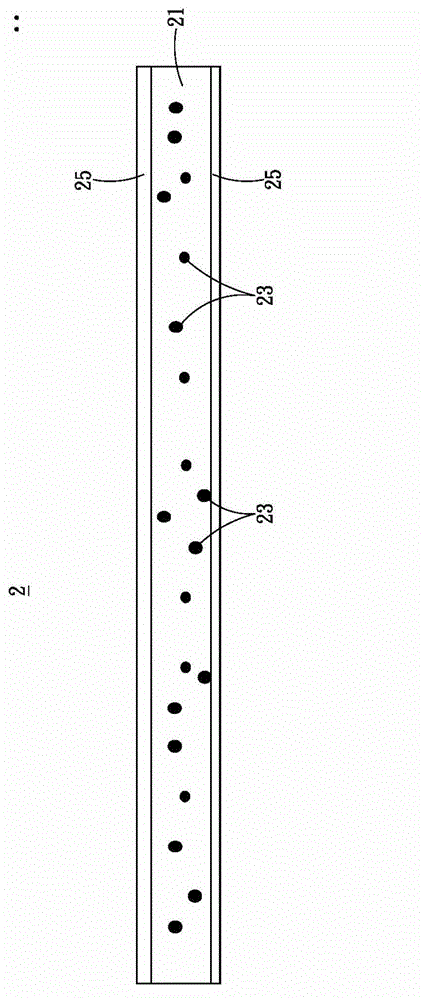
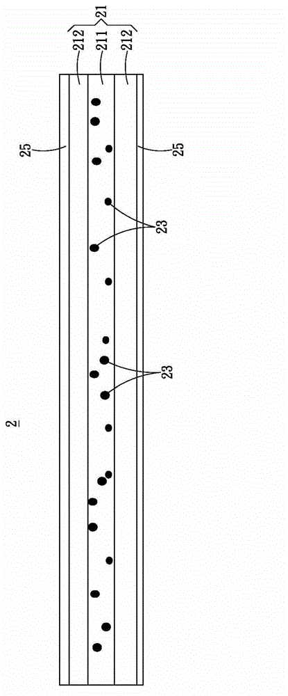
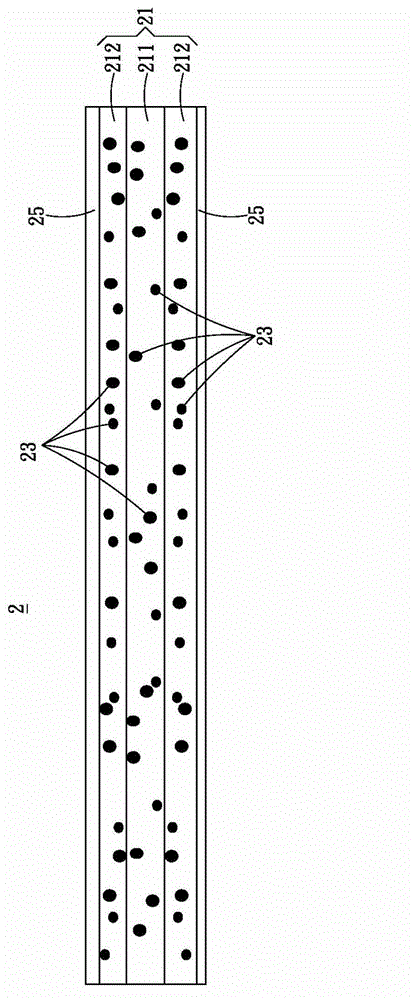
[0031] figure 1 and figure 2 , is an embodiment of the light source diffusion structure of the present invention. figure 1 A cross-sectional schematic diagram of the diffuser plate, figure 2 Schematic diagram of a cross-section of a diffuser.

[0032] Such as figure 1 and figure 2 , The light source diffusion structure 2 of the present invention includes a diffusion body 21 , a plurality of quantum dot phosphors 23 , and a plurality of water and air barrier layers 25 .

[0033] In some implementations, such as figure 1 As shown, the light source diffusion structure 2 is a diffusion plate. Here, a plurality of quantum dot phosphors 23 are uniformly dispersed in the diffusion body 21, and water-repelling air layers 25 are respectively provided on the surface of the diffusion body 21 to prevent water vapor from causing the luminous intensity of the quantum dot phosphors 23. decline.

[0034] In some implementations, such as figure 2 As shown, the light source diffusi...


PUM

PropertyMeasurementUnit
Sizeaaaaaaaaaa
Sizeaaaaaaaaaa

Abstract

The invention provides a direct type backlight module and a light source diffusion structure thereof, wherein the light diffusion structure comprises a diffusion body, a plurality of quantum dot phosphor powders and a plurality of moisture resistance layers; the quantum dot phosphor powders are diffused in the diffusion body; and the moisture resistance layers are positioned on a surface of the diffusion body. The quantum dot phosphor powders are diffused in the diffusion body of a diffusion board or a diffusion sheet, so service life is prolonged and light recession is retarded.

Description

technical field [0001] The invention relates to a backlight module, in particular to a direct-type backlight module and a light source diffusion structure thereof. Background technique [0002] The liquid crystal panel emits light through the light processing element of the backlight module to enter the light incident surface of the light guide plate. Wherein, the light processing element can be made of glass or plastic, and the light processing element is filled with fluorescent powder as a wavelength conversion material. Based on this, the light processing element converts a part of the light source emitted by the light emitting element into a light source of another wavelength and mixes it with the remaining light source emitted by the light emitting element to emit white light. [0003] Wherein, the phosphor powder filled in the light processing element can be classified into inorganic phosphor powder or organic phosphor powder. Also, there are currently light processi...

Claims


Application Information

Patent Timeline
IPC IPC(8): F21V5/08F21V9/10F21S8/00F21Y101/02F21V9/40F21Y115/10
Inventor 陈明伦杜福安谢坤宏
Owner AU OPTRONICS CORP
Learn More