High temperature pipeline wall thickness on-line monitoring device

A monitoring device and pipeline wall technology, applied in measuring devices, instruments, using ultrasonic/sonic/infrasonic waves, etc., can solve the problems of long preparation period, waste of maintenance time, poor high temperature resistance, etc., to prevent unplanned downtime, reduce The effect of detection cost and high temperature resistance range

Active Publication Date: 2013-03-20
ZHEJIANG SCI-TECH UNIV
View PDF4 Cites 20 Cited by
  • Summary
  • Abstract
  • Description
  • Claims
  • Application Information

AI Technical Summary

Problems solved by technology

[0004] 1. The high temperature resistance of the ultrasonic probe is poor: Generally, the ultrasonic probe uses a piezoelectric ceramic chip, which has poor continuous high temperature resistance, and the measurement error is greatly affected by the temperature;
[0005] 2. Short single measurement time: Under high temperature conditions, the ultrasonic couplant evaporates in only a few seconds, resulting in a very short contact time between the probe and the high-temperature pipeline. It takes repeated measurements to obtain rela

Method used


Image

  • High temperature pipeline wall thickness on-line monitoring device
  • High temperature pipeline wall thickness on-line monitoring device

Examples


Embodiment

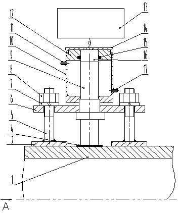
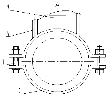
[0028] This embodiment is to measure a high-temperature pipeline at 500°C. The wall thickness of the high-temperature pipe 1 is 30mm, the working frequency of the ultrasonic probe 16 is 5MHz, the wafer diameter is 10mm, the optimum working temperature is 40°C, and the measuring range is 1.2mm-230mm. According to the empirical formula, the average sound velocity of the ultrasonic wave in the probe 9 is 5439m / s. The diameter of the top end of the probe 9 is 12 mm, the diameter of the bottom end is 16 mm, and the length is 120 mm. The copper sheet 4 has a thickness of 2mm. The cooling water temperature is 18°C. Heat the temperature of pipeline 1 to 500°C, and the flow rate from water inlet 17 is 0.75 m3.h -1 cooling water to reduce the temperature of the tip of the probe 9 to 40°C. Turn on the ultrasonic thickness measuring host 13, adjust the sound velocity to 5439m / s, contact the ultrasonic probe 16 with the top surface of the probe 9 immersed in water, seal it with the flu...


PUM

PropertyMeasurementUnit
Thicknessaaaaaaaaaa

Abstract

The invention discloses a high temperature pipeline wall thickness on-line monitoring device. A high temperature pipeline is clamped inside a pipe clamp. Bolts formed in a square shape are connected with the pipe clamp in a welded mode. A stepped type wave guiding rod is arranged in the middle portion of the square-shaped bolts. A cooper sheet is arranged on an end face of the wave guiding rod, facing to one side of the high temperature pipeline. After the bolts and the stepped appearance wave guiding rod penetrate through a pressing board, the bolts and the stepped appearance wave guiding rod are fixed and pressed on a shaft shoulder of the wave guiding rod through nuts. The end face on the other side of the wave guiding rod is provided with an ultrasonic probe and is placed in a water cooled sleeve. The lower end of the water cooled sleeve is in an interference fit with the shaft shoulder of the wave guiding rod. The ultrasonic probe is placed in a center hole of a plunger piston and is sealed. A big hole formed in the upper end of the water cooled sleeve is connected with the plunger piston and a pressing cover. The pressing cover is pressed on an end face of the ultrasonic probe. The ultrasonic probe is connected with an ultrasonic thickness monitoring main machine. The water cooled sleeve is provided with a water inlet and a water outlet. According to the high temperature pipeline wall thickness on-line monitoring device, high temperature thickness monitoring is converted indirectly into low temperature thickness monitoring through the copper sheet and the wave guiding rod, and therefore real time on-line monitoring of the high temperature pipeline wall thickness is achieved, production cost is low and popularizing is easy.

Description

technical field [0001] The invention relates to an on-line monitoring device, in particular to an on-line monitoring device for high-temperature pipeline wall thickness. Background technique [0002] As a special equipment for transporting multiphase flow media, high temperature pipelines are widely used in coal chemical industry, petrochemical industry, energy and electric power and other fields. Due to complex working conditions such as medium physical properties, flow patterns, flow states, and phase transitions, the piping system is prone to local wear and thinning, which in turn causes safety accidents such as medium leakage, explosion, and fire, and seriously hinders the long-term operation of the production line. In order to prevent unplanned shutdowns caused by local thinning failures of pipes, thickness monitoring must be carried out on parts of pipes that are prone to thinning. [0003] For the wall thickness monitoring methods of high-temperature pipelines in ser...

Claims


Application Information

Patent Timeline
IPC IPC(8): G01B17/02
Inventor 偶国富肖定浩李伟正秦良杰张文彪
Owner ZHEJIANG SCI-TECH UNIV
Why Eureka
Try Eureka