Screening machine filter shaft
A screening machine, screen shaft technology, applied in the direction of screen, solid separation, grille, etc., can solve the problem of material blocking and other problems
- Summary
- Abstract
- Description
- Claims
- Application Information
AI Technical Summary
Problems solved by technology
Method used
Image
Examples
Embodiment 1
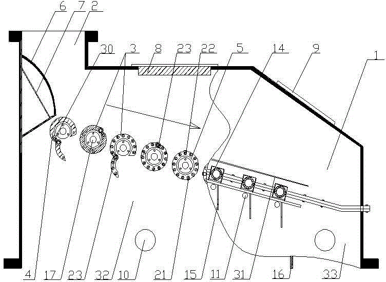
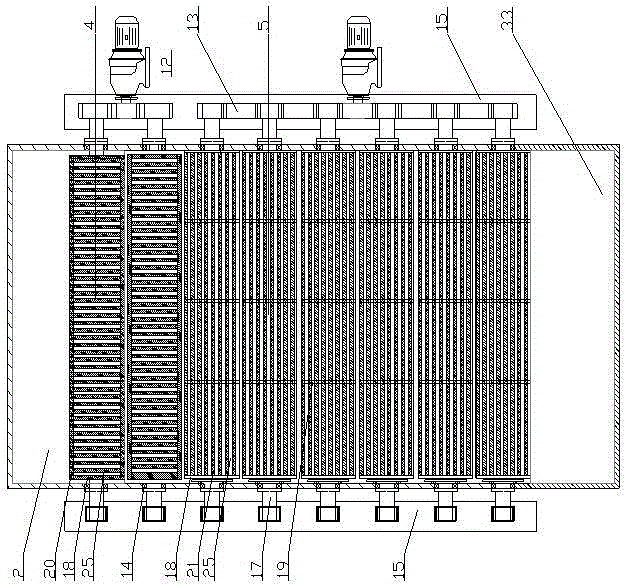
[0067] Embodiment 1: as figure 1 , figure 2As shown, the screening machine includes feed inlet 2, sieve shaft 3, flange-type sieve shaft 4, bar-type sieve shaft 5, arc distribution plate 6, distribution plate support 7, iron remover 8, inspection cover 9 , Particle size observation hole 10, sieve bar replacement hole 11, gear motor 12, gear 13, sealed bearing 14, support frame 15, particle size guide plate 16, transmission shaft 17, flange piece 18, reinforcement ring 19, clip bar 20. Sieve bar 21, sieve slit enlarged hole 22, filter sieve shaft bearing 23, sieve slit 25, bearing cover plate 29, qualified particle size discharge port 30, coarse particle size discharge port 31. The material is in the shape of a water column and falls from a high place onto the arc-shaped distribution plate 6 on the inner wall of the feed inlet 2, breaking the water column to complete the first distribution, and then the material falls on the flange plate sieve shaft 4, breaking the oval shape...
Embodiment 2
[0068] Embodiment 2: as image 3 As shown, the flange plate type screen shaft 4 includes flange plate 18, screen slot gap nut 27, filter screen shaft bearing 23, clip bar 20, transmission shaft 17, and is combined into a flange type screen shaft with screen slot 25 Screen shaft 4. The main functions of the flange plate screen shaft are impact resistance, conveying, material distribution, and screening; image 3 Obviously, the flange plate type screen shaft 4 is cut into several pieces of two groups of flange plate type screen shafts by several circular flange plates 18. One set of flanged screen shafts is fixed, while the other set of flanged screen shafts is movable. There are clips in the movable holes of the flanges 18 on the movable screen shafts. The clips 20 are String all the movable flanges on the top to form a movable half screen shaft. There are two kinds of activities on the movable half screen shaft. One uses the rotating screen shaft bearing 23, and the other us...
Embodiment 3
[0069] Embodiment 3: as Figure 4 , Figure 5 , Figure 6 , Figure 7 As shown, the sieve type sieve shaft includes a flange 18, a reinforcing ring 19, a sieve bar 21, a drive shaft 17, a filter sieve shaft bearing 23, a sieve slit enlargement hole 22, and a chain 28 to form a belt sieve 25 and a belt sieve hole. The sieve type sieve shaft 5. From Figure 4 , Figure 5 , Figure 6 , Figure 7 It is obvious that the sieve-type sieve shaft 5 is composed of flanges 18 and sieve bars 21, and the sieve-type sieve shaft 5 is also composed of two flanges with sieve bars 21 to form a circular sieve-type sieve shaft 5. One of the flanges with sieve bars is fixed, while the other flange with sieve bars is active. In the sieve type sieve shaft 5, a sieve shaft reinforcement ring 19 consistent with the flange sheet parameters is also provided, and the number of the reinforcement ring in each sieve type sieve shaft is 2-10; each sieve bar material, The diameter and length are not ...
PUM
 Abstract
Description
Claims
Application Information
 - R&D
- Intellectual Property
- Life Sciences
- Materials
- Tech Scout
- Unparalleled Data Quality
- Higher Quality Content
- 60% Fewer Hallucinations
Browse by: Latest US Patents, China's latest patents, Technical Efficacy Thesaurus, Application Domain, Technology Topic, Popular Technical Reports.
© 2025 PatSnap. All rights reserved.Legal|Privacy policy|Modern Slavery Act Transparency Statement|Sitemap|About US| Contact US: help@patsnap.com


