Forced shearing flying shear and forced shearing method thereof

A control method and technology of flying shears, which are applied in the direction of shearing devices, devices for shearing forming blanks, and shearing equipment, etc., can solve the problems of affecting the production of steel bars, failure to automatically shear, and leakage of cooling bed, etc., so as to reduce artificial The effect of working, simple structure, and reducing labor intensity

Active Publication Date: 2013-03-27
JIANGSU YONGGANG GROUP CO LTD
View PDF3 Cites 4 Cited by
  • Summary
  • Abstract
  • Description
  • Claims
  • Application Information

AI Technical Summary

Problems solved by technology

During the cutting process of the flying shears, if there is a fault in the thermal inspection after cutting (for example, there is always a signal of steel bars or no signal of steel bars), the flying shears will not be able to cut automatically, causing the cooling bed behind the finished machine to keep leaking, which seriously affects the The production of steel bars caused large economic losses

Method used


Image

  • Forced shearing flying shear and forced shearing method thereof
  • Forced shearing flying shear and forced shearing method thereof

Examples


Embodiment 1

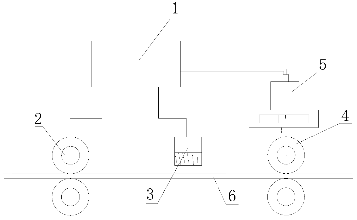
[0029] The forced shear flying shear of the present embodiment has a structure such as figure 1 As shown, it includes a DC motor 5, a reduction box, a flying shear body 4 and a scanning thermal detection device 3. The scanning thermal detection device 3 is aligned with the head of the rolled piece 6 on the finished product frame 2, and the scanning thermal detection device 3 The signal output end of the T400 process board 1 is connected to the signal input end of the T400 process board 1, the output end of the T400 process board 1 is connected to the controlled end of the flying shear body 4, and a positioning proximity switch is provided at the cutting edge of the flying shear body 4. In order to accurately locate the flying shear body, the signal output terminal of the positioning proximity switch is connected to the signal input terminal of the T400 process board 1, and the DC motor 5 is connected to the speed regulating device and the encoder. The speed regulating device ca...

Embodiment 2

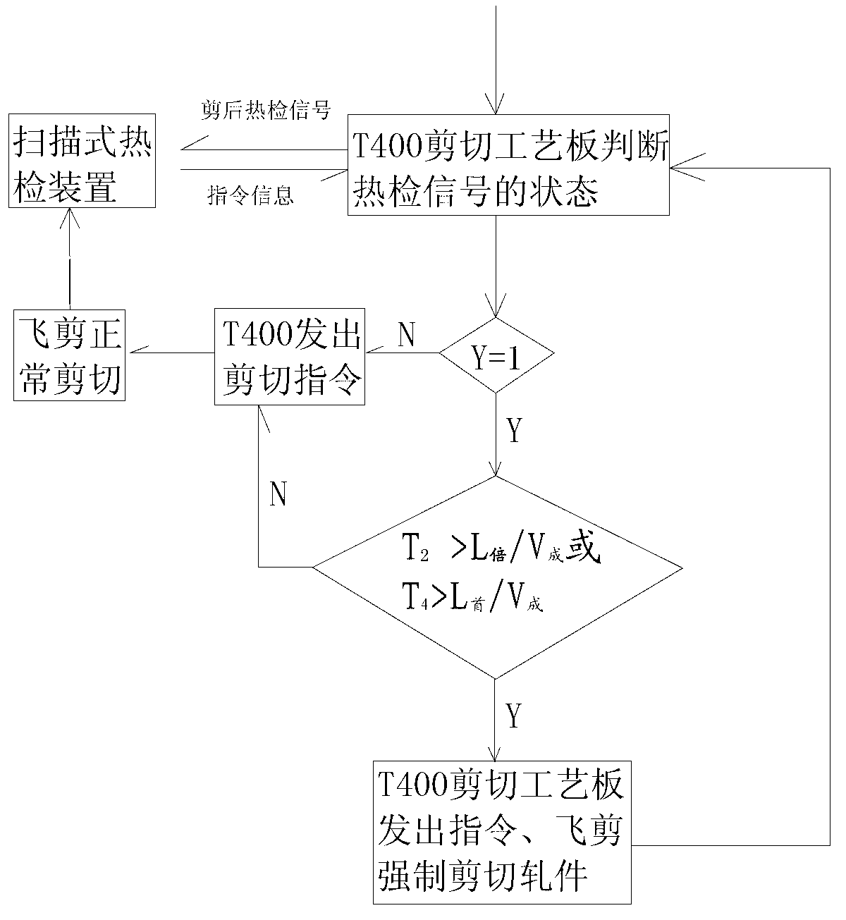
[0032] The difference between this embodiment and Embodiment 1 is that the T400 process board judges the time T, when "T≤L 倍 / V 成 ", the T400 process board sends a cutting command to the controlled end of the flying shear, and controls the flying shear to perform normal shearing on the rolled piece. After the operation is completed, it returns to the normal shearing state, enters step 1, and starts the next cycle. Among them, L 倍 Set to 96.30m, V 成 is 7 m / s.

Embodiment 3

[0034] The difference between this embodiment and Embodiment 1 is that the scanning thermal detection device conducts thermal detection on the rolled piece to obtain the signal Y, and transmits the signal Y to the T400 process board, and the T400 process board judges that "Y=0", The T400 process board sends a delayed cutting command to the controlled end of the flying shear, and the flying shear is delayed for a certain time T 1 Finally, normal shearing is carried out on the rolled piece, and the operation is completed, and the next cycle is entered. where T 1 =(L 倍 -L 45 ) / V 成 , L 倍 95.20 meters, L 45 for 45m, V 成 is 6 m / s.


PUM


Abstract

The invention relates to a forced shearing method of a forced shearing flying shear. The method comprises the following steps of conducting hot detection on a rolled piece by using a scanning type hot detection device after shearing to obtain a signal Y, setting the normal state of the signal Y to be 0 and the fault state to be 1, judging the state of the signal obtained through hot detecting the rolled piece after shearing by using a process plate T400 according to a formula (1), if Y=1, implanting the second step, and if Y=0, sending a delayed shearing instruction to a controlled end of the flying shear by the process plate T400, shearing the rolled piece by using the flying shear after the flying shear is delayed for a certain time T1, and ending the operation; setting the time difference between two shearing actions of the flying shear to be T2, judging whether the flying shear needs to forcedly shear the rolled piece according to a formula (2), if T2 is more than L (double-ruler set length) / V (finished product rack linear velocity), implementing the third step, if T2 is smaller than or equal to L (double-ruler set length) / V (finished product rack linear velocity), sending a shearing instruction to the controlled end of the flying shear by using the process plate T400, shearing the rolled piece by using the flying shear, and ending the operation; and sending a forced shearing instruction to the controlled end of the flying shear by the process plate T400, forcedly shearing the rolled piece for a certain length L (forced shearing length) by using the flying shear, stopping the operation and implementing the next circulation.

Description

technical field [0001] The invention relates to a forced shearing flying shear, and also relates to a forced shearing method thereof. Background technique [0002] Flying shear is one of the important equipment in the rod and wire rolling system. After the steel bar enters the finished machine, it needs to go through the thermal inspection before shearing and the thermal shear after shearing in sequence. When the thermal inspection before shearing and the thermal inspection after shearing can detect the signal of the steel bar , the flying shears are delayed for a certain period of time to cut, and the DC motor drives the reduction box to rotate every time the flying shears move. During the cutting process of flying shears, if there is a fault in the thermal inspection after cutting (for example, there is always a signal of steel bar or no signal of steel bar), the flying shear will not be able to cut automatically, causing the cooling bed behind the finished machine to keep...

Claims


Application Information

Patent Timeline
Patent Type & Authority Applications(China)
IPC IPC(8): B23D25/02B23Q15/00
Inventor 冯建峰蒋志兵丁燕新梁柏林苏倩
Owner JIANGSU YONGGANG GROUP CO LTD
Why Eureka
Try Eureka