Method for vacuum assembling and non-vacuum rolling laminated metal composite material roll

A metal material and laminated metal technology, applied in the field of steel rolling, can solve the problems of broken composite coils, damage to heating furnaces, rolling mills and other equipment, and the inability to discharge the air of composite slabs. The effect of protecting normal production

Active Publication Date: 2013-03-27
云南昆钢新型复合材料开发有限公司
View PDF5 Cites 20 Cited by
  • Summary
  • Abstract
  • Description
  • Claims
  • Application Information

AI Technical Summary

Problems solved by technology

[0005] In order to solve the problem that the residual air in the composite slab cannot be discharged, resulting in a sudden increase in pressure, causing the composite coil to be broken, and causing damage to the heating furnace, rolling

Method used


Image

  • Method for vacuum assembling and non-vacuum rolling laminated metal composite material roll
  • Method for vacuum assembling and non-vacuum rolling laminated metal composite material roll
  • Method for vacuum assembling and non-vacuum rolling laminated metal composite material roll

Examples


Embodiment 1

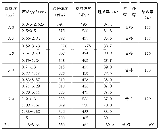
[0022] Carbon steel plate Q235B is selected as the base metal material, stainless steel plate 06Cr19Ni10 (SUS304) is used as the cladding metal material, and multiple batches of treatment are carried out respectively, and each batch is carried out according to the following method:

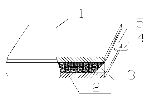
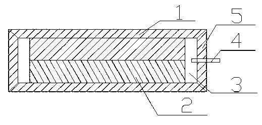
[0023] (1) Composite slab welding and sealing: the clad metal material 2 and base metal material 1 are surface treated by conventional mechanical methods until the joint interface is clean, and then the clad metal material 2 formed by stacking two pieces is placed on the Between the upper and lower base metal materials 1, and reserve a rolling extension space 3 around the clad metal material 2, use the base metal material 1 as the four side walls, and weld with the upper and lower base metal materials 1 to form a hollow body, so that the cladding metal material 2 is placed in the hollow body of the base metal material after sealing and welding to obtain a composite billet; holes are opened at inter...

Embodiment 2

[0027] Select stainless steel plate 12Cr17Mn6Ni5N (SUS201) as the base metal material, and stainless steel plate 06Cr19Ni10 (SUS304) as the cladding metal material, and carry out multiple batches of treatment, and each batch is carried out according to the following method:

[0028] (1) Composite slab welding and sealing: the clad metal material 2 and base metal material 1 are surface treated by conventional mechanical methods until the joint interface is clean, and then the clad metal material 2 formed by stacking two pieces is placed on the Between the upper and lower base metal materials 1, and reserve a rolling extension space 3 around the clad metal material 2, use the base metal material 1 as the four side walls, and weld with the upper and lower base metal materials 1 to form a hollow body , the clad metal material 2 is placed in the hollow body of the base metal material after sealing and welding to obtain a composite blank, and holes are spaced on the tail end side wal...


PUM

PropertyMeasurementUnit
Thicknessaaaaaaaaaa

Abstract

The invention provides a production method of rolled laminated metal composite roll, in which laminated metal composite blank is in vacuum state before assembling and rolling and in non-vacuum state in the hot rolling process. The method is characterized in that the inner end of an aluminum hollow pipe segment enters a reserved rolling extension space in the composite blank, the other end is connected with a vacuum pump; and the composite blank is evacuated through the vacuum pump and the pipe segment. The method can ensure the high vacuum degree in the composite blank before rolling, and can keep the internal junction surface of the composite blank clean and prevent oxidation. The method can ensure that air is discharged in time, thereby radically solving the problems of the prior art caused by the difficulty in discharging air in the composite blank, such as surface damages of the composite rolls or even damages to rolling equipment. The laminated metal composite material roll prepared by the method has the advantages of high strength, good mechanical processing performance, high corrosion resistance, high surface decorativeness, high quality and low production cost.

Description

technical field [0001] The invention relates to a method for rolling a laminated metal composite plate, in particular to a method for vacuum forming blanks-non-vacuum rolling laminated metal composite coils, which belongs to the technical field of steel rolling. Background technique [0002] Hot-rolled laminated metal composite coil refers to the metal clad layer such as stainless steel plate and the metal base layer such as carbon steel plate welded to form a composite billet, and then the composite billet is hot-rolled to obtain a metal composite coil. The basic principle is to bond two metal layers with clean surfaces to each other and weld them along the periphery to make a composite slab, and make the composite slab under a certain temperature and rolling pressure to realize the metallurgy of the base layer and the clad layer metal. In combination, its production process is generally: billet assembly-rolling-post-treatment. [0003] The hot-rolled laminated metal compo...

Claims


Application Information

Patent Timeline
IPC IPC(8): B23P17/00
Inventor 杜顺林李志刚赵知明王庭昆张凤珍吴天玖吴文平朱永安仇万福杜九红
Owner 云南昆钢新型复合材料开发有限公司
Why Eureka
Try Eureka