Engine balance shaft system

A balance shaft and engine technology, applied in the direction of eccentric shaft, inertial force compensation, etc., can solve the problems of inconvenient layout, jamming, easy deformation, etc., and achieve the effect of easy layout, lower overall height, and lower failure rate

Active Publication Date: 2013-03-27
CHERY AUTOMOBILE CO LTD
View PDF7 Cites 13 Cited by
  • Summary
  • Abstract
  • Description
  • Claims
  • Application Information

AI Technical Summary

Problems solved by technology

[0005] The purpose of this invention is to propose an engine balance shaft system to solve the problems of inconvenient arrangement, easy deformation and jamming of the traditional balance shaft system

Method used


Image

  • Engine balance shaft system
  • Engine balance shaft system
  • Engine balance shaft system

Examples


Embodiment 1

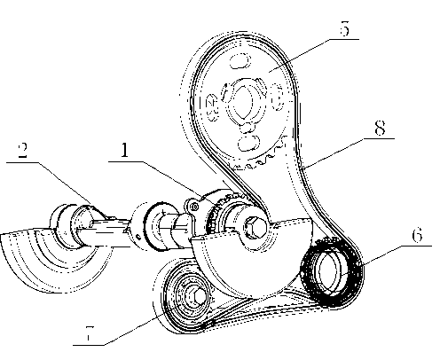
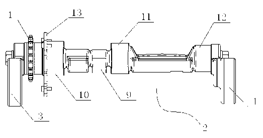
[0020] As shown in the figure, the engine balance shaft system of this embodiment includes a balance shaft 2 equipped with a balance shaft sprocket 1, a front balance weight 3 and a rear balance weight 4 are arranged on the balance shaft 2, and the balance shaft sprocket 1 is arranged on the machine. Inside the triangle formed by oil pump drive sprocket 5, crankshaft timing sprocket 6, and camshaft drive sprocket 7, the balance shaft sprocket 1, oil pump drive sprocket 5, crankshaft timing sprocket 6, and camshaft drive Sprocket 7 is on the same plane and is linked with timing chain 8, and guarantees that the rotational angular velocity of balance shaft 2 and crankshaft is consistent, and direction is opposite.

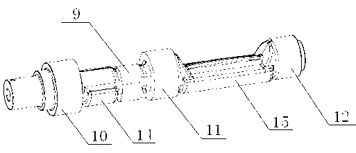
[0021] A fuel pump driving cam 9 is arranged on the balance shaft 2 . The fuel pump driving cam 9 and the balance shaft 2 are designed to be integrated, which can simplify the driving system of the fuel pump, remove parts such as gears, reduce transmission friction, a...


PUM


Abstract

The invention aims to provide an engine balance shaft system for solving the problems that a traditional balance shaft system is inconvenient to arrange and prone to deforming and being stuck. The engine balance shaft system disclosed by the invention comprises a balance shaft with a balance shaft chain wheel, wherein the balance shaft is provided with a front balance block and a rear balance block. The engine balance shaft system is characterized in that the balance shaft chain wheel is arranged inside a triangle formed by a fuel pump drive chain wheel, a crankshaft timing chain wheel and a camshaft drive chain wheel; and the balance shaft chain wheel, the fuel pump drive chain wheel, the crankshaft timing chain wheel and the camshaft drive chain wheel are on a same plane and are chained by timing chains. Therefore, the whole structure of the engine balance shaft system is simpler. Simultaneously, the balance shaft is arranged on one side of a crankshaft rather than below the crankshaft, so that the whole height of the engine balance shaft system can be reduced, and the engine balance shaft system is easier to arrange.

Description

technical field [0001] The invention relates to an automobile engine, and more particularly relates to an engine balance shaft system. Background technique [0002] The balance shaft system and oil pump of the traditional two-cylinder engine are installed in the oil pan, and the oil pump is coaxial with the crankshaft, which leads to a very high engine height, which is not conducive to the overall layout of the vehicle. It is difficult to arrange the crankshaft, balance shaft, oil pump and camshaft on the same sprocket train, and there may be multiple sprockets. Since the balance shaft and the crankshaft rotate in the opposite direction, it is necessary to use some idler gears to make the gear train more efficient. for complex. [0003] A traditional engine uses a camshaft to drive a high-pressure oil pump, and the plunger of the pulsed oil pump exerts a very large oil pressure on the camshaft, which has high requirements on the strength of the camshaft. At the same time,...

Claims


Application Information

Patent Timeline
Patent Type & Authority Applications(China)
IPC IPC(8): F16F15/26F16C3/18
Inventor 李为松张欣林
Owner CHERY AUTOMOBILE CO LTD
Why Eureka
Try Eureka