Antireflection optical assembly and manufacturing method thereof

A technology of optical components and manufacturing methods, applied in the field of nanomaterials, can solve the problems of poor stability of anti-reflection layer, low mechanical strength, short service life of anti-reflection layer, etc.

Inactive Publication Date: 2013-03-27
SAINT-GOBAIN GLASS FRANCE
View PDF7 Cites 22 Cited by
  • Summary
  • Abstract
  • Description
  • Claims
  • Application Information

AI Technical Summary

Problems solved by technology

[0011] However, due to the relatively high activity of zinc oxide, it is easy to chemically react with acidic substances or alkaline substances, and its mechanical strength is low, so the stability of the anti-reflection layer is relatively poor, and finally the service life of the anti-reflection layer is relatively short.

Method used


Image

  • Antireflection optical assembly and manufacturing method thereof
  • Antireflection optical assembly and manufacturing method thereof
  • Antireflection optical assembly and manufacturing method thereof

Examples


Embodiment Construction

[0045] In order to make the above objects, features and advantages of the present invention more comprehensible, specific implementations of the present invention will be described in detail below in conjunction with the accompanying drawings.

[0046] In the following description, many specific details are set forth in order to fully understand the present invention, but the present invention can also be implemented in other ways than those described here, so the present invention is not limited by the specific embodiments disclosed below.

[0047] In the following, product embodiments are described with reference to method embodiments for exemplary purposes. However, it should be understood that the products and methods of the present invention are implemented independently of each other. That is, the disclosed product embodiments can be prepared according to other methods, and the disclosed method embodiments are not limited to realizing the product embodiments.

[0048]Th...


PUM

PropertyMeasurementUnit
thicknessaaaaaaaaaa
thicknessaaaaaaaaaa
thicknessaaaaaaaaaa

Abstract

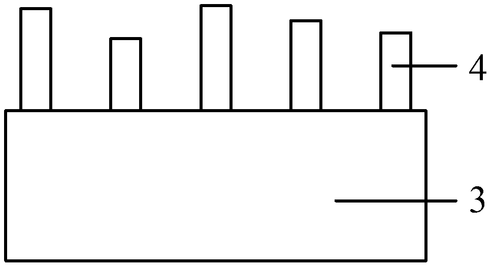
Provided are an antireflection optical assembly and a manufacturing method thereof. The antireflection optical assembly comprises a substrate, an antireflection layer located on the surface of the substrate and a covering layer located on the surface of the antireflection layer, wherein the antireflection layer comprises a zinc oxide nanorod array composed of a plurality of zinc oxide nanorods, and the covering layer is made of one or more of silicon oxide, titanium oxide, aluminum oxide and zirconium oxide. The manufacturing method comprises providing the substrate, enabling the antireflection layer with a moth eye structure to be formed on the surface of the substrate, and enabling the covering layer to be formed on the surface of the antireflection layer, wherein the antireflection layer comprises a protrusion array composed of a plurality of protrusions, and the covering layer is made of one or more of silicon oxide, titanium oxide, aluminum oxide and zirconium oxide.

Description

technical field [0001] The invention relates to the technical field of nanomaterials, in particular to an anti-reflection optical component and a manufacturing method. Background technique [0002] When light is propagating, a part of the interface between different media usually changes its propagation direction and returns to the original medium, which is called light reflection. In general, the greater the difference in refractive index between different media, the more strongly light will be reflected at that interface. In the fields of photovoltaic devices and displays, how to reduce the reflection of light has always been a research hotspot. [0003] The compound eyes of moths can be viewed as an array of hexagonal nanostructure protrusions. The array is thought of as a homogeneous transparent layer on the corneal surface, with each nanostructured bump acting as an antireflection unit. This structure makes the moth's compound eyes less reflective, making them appear...

Claims


Application Information

Patent Timeline
Patent Type & Authority Applications(China)
IPC IPC(8): G02B1/11G02B1/118
Inventor 谷鋆鑫
Owner SAINT-GOBAIN GLASS FRANCE
Why Eureka
Try Eureka