MAS-based simulation method for multi-microgrid energy management system

An energy management system and multi-microgrid technology, applied in the field of energy control and management system simulation, can solve problems such as increasing the complexity of system energy control scheduling decisions, increasing the amount of energy control and management information, and increasing the complexity of microgrid scheduling problems. , to achieve the effect of easy real-time energy management and control, convenient effect evaluation, and flexible design

Active Publication Date: 2014-10-08
HEFEI UNIV OF TECH
View PDF3 Cites 2 Cited by
  • Summary
  • Abstract
  • Description
  • Claims
  • Application Information

AI Technical Summary

Problems solved by technology

[0003] 1. Diversity of power generation units: Since the load-following response speed of each power generation unit in the microgrid varies greatly, from millisecond level (solar energy, fuel cell, electric energy storage equipment), second level (gas turbine, mechanical energy storage) to graded (Wind power generation), and the correlation of input energy (such as wind energy, solar energy) and output energy (power supply) increase the complexity of microgrid operation and scheduling problems, greatly increasing the amount of information for energy control and management
[0004] 2. The volatility of primary energy: due to the randomness of solar and wind energy, the actual power generation capacity of the microgrid system including solar power and wind power generation units is random and fluctuating, making the system energy scheduling compared with the power system, not only needs To accurately predict the demand of load, it is also necessary to accurately predict the power generation capacity (short-term and long-term) of solar and wind power generation units, which will greatly increase the complexity of system energy control and scheduling decisions
The verification of the above method needs to provide effective and economical means, but so far there is no public report of related technology

Method used


Image

  • MAS-based simulation method for multi-microgrid energy management system
  • MAS-based simulation method for multi-microgrid energy management system
  • MAS-based simulation method for multi-microgrid energy management system

Examples


Embodiment Construction

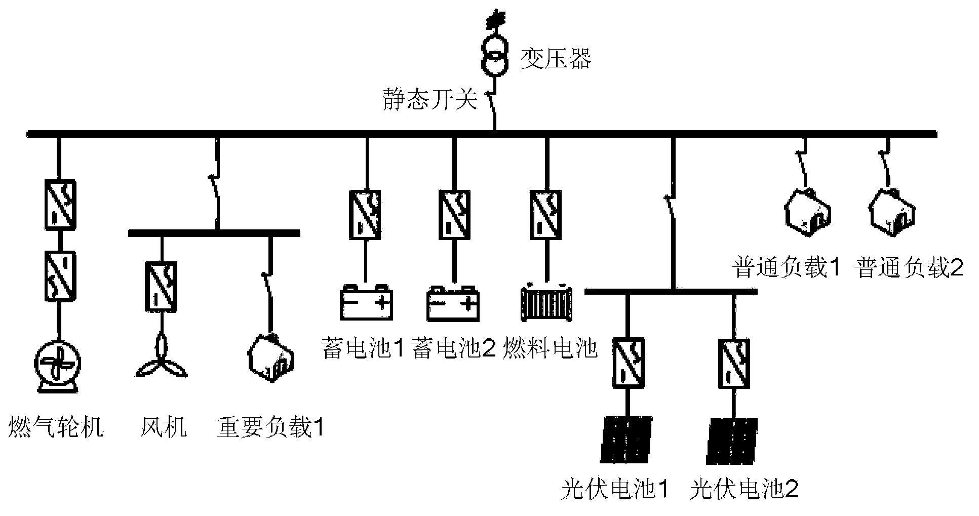
[0055] For micro-grid systems composed of photovoltaic power generation, wind power generation, fuel cells, micro-gas turbines and other micro-power generation systems, energy storage units such as lead-acid batteries and supercapacitors, and AC loads and DC loads (such as figure 2 Shown) to illustrate the specific implementation of the present invention. The equipment configuration used in the considered microgrid is shown in Table 1:

[0056] Table 1. Microgrid Configuration Parameters

[0057]

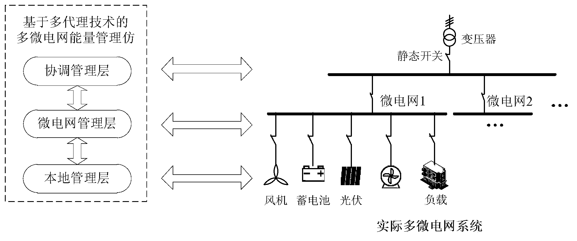
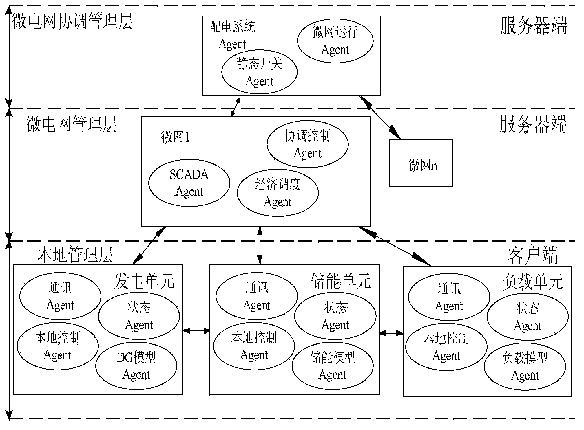
[0058] right figure 1 For the microgrid system shown, design a multi-agent energy management system model and simulation system, such as image 3 As shown, the multi-agent energy management system model includes local management, microgrid management and microgrid coordination management. The design of each energy layer is as follows:

[0059] 1. Agent design for local management

[0060] Local management modules corresponding to the corresponding distributed power generati...


PUM


Abstract

The invention relates to an MAS-based (multi-agent system) multi-microgrid energy management system simulation method. The method is characterized in that a multi-microgrid energy management system is divided into a local management layer, a microgrid management layer and a microgrid coordinated management layer in different levels; various energy management functions of the different layers are used to establish a multi-microgrid energy management system model by different types of agents, and agent communication protocol is designed for coordination and convention of the agents. The agents in different control layers of the local management layer, the microgrid management layer and the coordinated management layer are integrated by a client-server architecture, and accordingly an MAT-based (multi-agent technology-based) multi-microgrid energy management system simulation platform is formed. The method is provided to verify different microgrid control strategies and scheduling plans.

Description

technical field [0001] The invention relates to an energy control and management system simulation method applied in a micro grid system. Background technique [0002] Microgrid usually consists of renewable energy power generation systems such as wind energy, solar energy and biomass energy, clean energy power generation systems such as fuel cells and micro gas turbines, long-term and short-term energy storage devices such as batteries and flywheels, and various electrical loads and Composition of heat load. The purpose of the microgrid energy management system (EMS-MG) is how to maintain the stable operation of the microgrid and improve the efficiency of energy utilization of power generation equipment in the microgrid under the premise of meeting the electrical load and thermal load requirements of users in the microgrid; here On this basis, through accurate weather forecast data, the utilization rate of renewable energy such as wind energy and solar energy in the microg...

Claims


Application Information

Patent Timeline
Patent Type & Authority Patents(China)
IPC IPC(8): H02J3/06
Inventor 茆美琴金鹏杜燕汪海宁张健苏建徽张国荣
Owner HEFEI UNIV OF TECH
Why Eureka
Try Eureka