Steel-wire belt cut-off device for square-section bead ring

A technology of cutting device and traveler, applied in the field of steel belt devices, can solve the problems of frequent movements, heavy maintenance work, large impact noise, etc., and achieve the effect of eliminating potential safety hazards and saving equipment operating costs.

Active Publication Date: 2013-04-03
AEOLUS TIRE
View PDF9 Cites 2 Cited by
  • Summary
  • Abstract
  • Description
  • Claims
  • Application Information

AI Technical Summary

Problems solved by technology

[0008] ⑴There are serious safety hazards
Due to the large stroke range of the cutter (more than 120mm) and the limitation of the space position, safety protection facilities such as protective covers cannot be installed on this part, so it is easy to cause mechanical injury to the employee during the process of falling and lifting the cutter
[0009] ⑵There are many failure points and high failure rate, which affect the normal production
Each shift of the cutter has to move more than 3,000 times. Due to frequent movements and strong impact, it often occurs that the cutter is not working properly due to excessive wear and tear on the cutter fixing frame 3, the piston rod head of the cylinder 4, and the pin shaft 5. Work
[0010] (3) Large maintenance workload, high maintenance costs, and increased production costs
In addition to the above-mentioned faults affecting production, the alloy blade welded to the cutter and machine nozzle by brazing often breaks under frequent impacts, thereby increasing equipment operating costs
[0011] ⑷ During the working process of the cutter falling, cutting and lifting, a lot of impact noise is generated, which affects the physical and mental health of employees

Method used


Image

  • Steel-wire belt cut-off device for square-section bead ring
  • Steel-wire belt cut-off device for square-section bead ring
  • Steel-wire belt cut-off device for square-section bead ring

Examples


Embodiment Construction

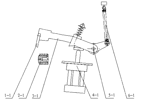
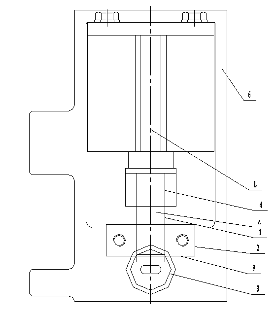
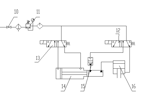
[0027] Such as figure 2 , image 3 and Figure 4 A steel wire cutting device for a square-section traveler is shown, which consists of two parts: an actuator and a gas-hydraulic power system. The actuator consists of a mounting frame 6, a machine nozzle 3, a cutter 1, a hydraulic cylinder 5, and a cutter joint 4 The machine nozzle 3 is arranged at the bottom of the installation frame 6, the hydraulic cylinder 5 is arranged at the top of the installation frame, the cutter 1 is installed on the piston rod 8 of the hydraulic cylinder through the cutter joint 4, and the cutter blade 9 and the cutter The plane a where the knife is located coincides with the plane passing through the center line L of the piston rod. The cutter blade 9 corresponds to the outlet of the machine nozzle. The gas-hydraulic power system is connected to the hydraulic cylinder 5. The cutter at the lower part of the piston rod cuts off the steel wire coming out of the nozzle. The installation frame of hyd...


PUM


Abstract

The invention discloses a steel-wire belt cut-off device for a square-section bead ring. The device comprises an actuating mechanism and a gas-liquid power system, wherein the actuating mechanism consists of a mounting bracket, a machine nozzle, a cutter, an oil hydraulic cylinder and a cutter connector; the machine nozzle is formed at the lower part of the mounting bracket; the oil hydraulic cylinder is arranged at the upper part of the mounting bracket; the cutter is arranged on a piston rod of the oil hydraulic cylinder through the cutter connector, and a plane Alpha on which a cutter blade and the cutter are arranged is coincided with a plane penetrating the centerline L of the piston rod; the cutter blade corresponds to the outlet of the machine nozzle; the gas-liquid power system is connected with the oil hydraulic cylinder; and the gas-liquid power system is used for pushing the piston rod to move up and down to drive the cutter at the lower part of the piston rod to cut off the steel-wire belt coming out of the machine nozzle. According to the invention, the travel of the cut-off cutter is less than 10 mm, and the device can conduct closed operation to completely eliminate security risks. The service life of the cutter and the machine nozzle is 3-5 times longer than that of similar devices.

Description

technical field [0001] The invention belongs to a cutting device for cutting a steel wire belt, in particular to a device for cutting a steel wire belt used for a steel wire ring with a square section. Background technique [0002] XJL—LG series tire bead ring winding extrusion production line is used for the production of square-section bead rings such as truck tires and construction machinery tires. The cutter device of the equipment has defects such as poor operating safety, high failure rate, and high noise during use, which not only affects the normal production, but also poses hidden dangers to the health and safety of operators. [0003] Its specific analysis is as follows: [0004] Equipment original cutter device such as figure 1 As shown, it is made up of cutter 1-1, machine nozzle 2-1, cutter fixed mount 3-1, lifting cutter cylinder 4-1, bearing pin 5-1 and tension spring 6-1 etc. [0005] It works as follows: [0006] After the winding disk reaches the set nu...

Claims


Application Information

Patent Timeline
Patent Type & Authority Applications(China)
IPC IPC(8): B21F11/00
Inventor 张陆军何清滨张军赵松善崔海云张洪海陈志高
Owner AEOLUS TIRE
Why Eureka
Try Eureka