Steel ingot vacuum casting device

A technology of vacuum pouring and steel ingots, applied in ingot workshops, manufacturing tools, casting workshops, etc., can solve problems such as difficulties in production organization and operation, influence of molten steel yield, ingot shape restrictions, etc., to achieve stable operation and improve molten steel Yield rate, effect of reducing consumption

Inactive Publication Date: 2013-04-03
JIANGSU YONGGANG GROUP CO LTD
View PDF4 Cites 10 Cited by
  • Summary
  • Abstract
  • Description
  • Claims
  • Application Information

AI Technical Summary

Problems solved by technology

On the one hand, the casting ingot shape is limited, on the other hand, the yield of molten steel is also greatly affected by this (because 2 tundishes are used)
If the remaining molten steel needs t

Method used


Image

  • Steel ingot vacuum casting device
  • Steel ingot vacuum casting device

Examples


Embodiment 1

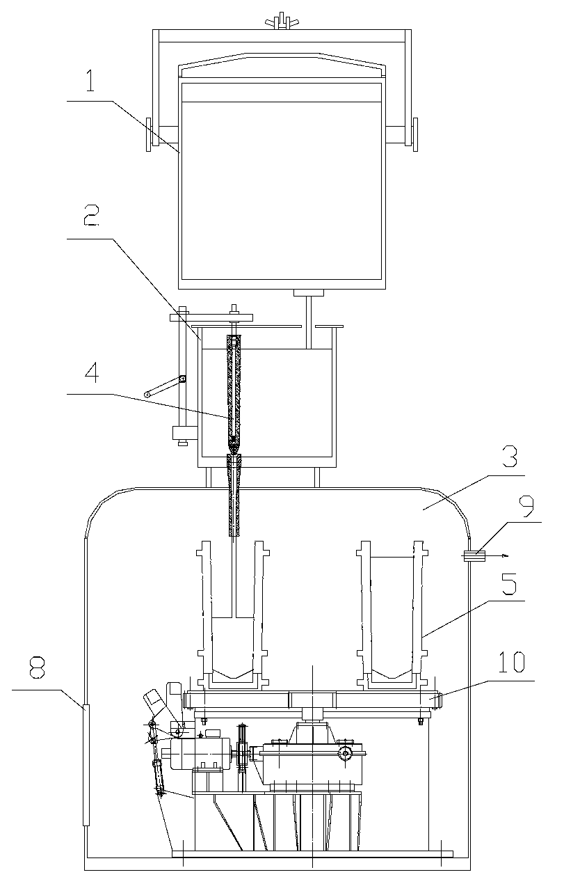
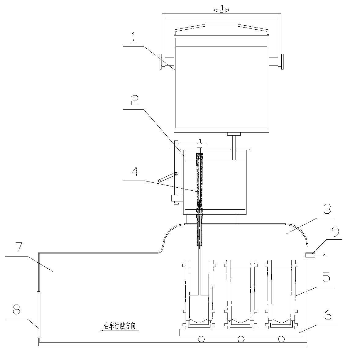
[0014] This embodiment is a vacuum pouring device for steel ingots, with a structure such as figure 1 As shown, it includes a refining bag 1, a tundish 2 arranged under the refining bag 1, and a vacuum tank 3 arranged under the tundish 2. The tundish 2 is connected to the vacuum tank 3 through a stopper rod 4, and multiple vacuum tanks are arranged in the vacuum tank 3. A steel ingot mold 5, a plurality of steel ingot molds 5 are arranged on a mobile trolley 6 and lined up, and when a certain steel ingot mold was positioned at the casting station, it was just below the stopper rod 4. The vacuum tank 3 is connected with a trolley chamber 7, the length of the trolley chamber 7 is greater than the length of the vacuum tank 3, and the height of the trolley chamber 7 is less than the height of the vacuum tank 3. An inspection hole 8 is provided on the trolley chamber 7 , and a gas discharge hole 9 is provided on the vacuum tank 3 .

[0015] When the present invention is specifical...

Embodiment 2

[0017] This embodiment is a vacuum pouring device for steel ingots, with a structure such as figure 2 As shown, it includes a refining bag 1, a tundish 2 arranged under the refining bag 1, and a vacuum tank 3 arranged under the tundish 2. The tundish 2 is connected to the vacuum tank 3 through a stopper rod 4, and multiple vacuum tanks are arranged in the vacuum tank 3. A steel ingot mold 5, a plurality of steel ingot molds 5 are arranged on a rotary platform 10, and are arranged circumferentially on the rotary platform 10. When a certain steel ingot mold is positioned at the pouring station, it is just below the stopper rod 4. An inspection hole 8 is provided on the vacuum tank 3 , and a gas discharge hole 9 is provided on the vacuum tank 3 .

[0018] When the present invention is specifically used, when the first steel ingot mold is located at the pouring station, it is just below the stopper rod 4. After the first steel ingot mold is poured, the rotation of the rotary plat...


PUM


Abstract

The invention relates to a casting device, in particular to a steel ingot vacuum casting device. The steel ingot vacuum casting device comprises a refining ladle, a middle ladle and a vacuum tank, wherein the middle ladle is arranged below the refining ladle; the vacuum tank is arranged below the middle ladle; the middle ladle is connected with the vacuum tank through a plug rod; at least two steel ingot dies are arranged in the vacuum tank, are arranged on a moveable trolley in one line or are peripherally arranged on a rotary platform; and when one steel ingot die is positioned at a casting station, the steel ingot die is positioned right below the plug rod. The steel ingot vacuum casting device is simple in structure, flexible and variable. The requirement of casting a plurality of steel ingots by one vacuum chamber and one middle ladle can be completely met, the yield of molten steel is improved, the consumption of the middle ladle is reduced, the stable running of a production organization is facilitated, and the production and running cost is low.

Description

technical field [0001] The invention relates to a pouring device, in particular to a vacuum pouring device for steel ingots. Background technique [0002] The steel ingot vacuum pouring device includes a refining ladle, a tundish arranged under the refining ladle, and a vacuum tank arranged under the tundish. The existing steel ingot vacuum pouring device is provided with an ingot mold in the vacuum tank below the stopper rod in the tundish , for pouring steel ingots, only one steel ingot can be poured at a time. When producing steel ingots in large electric furnaces or converters with a capacity of about 100 tons, in order to meet the requirements of different users, the casting ingot shapes are different. The steel ingot vacuum pouring device casts 2 steel ingots. On the one hand, the casting ingot shape is limited, and on the other hand, the yield of molten steel is also greatly affected by this (because 2 tundishes are used). If the remaining molten steel needs to be ...

Claims


Application Information

Patent Timeline
IPC IPC(8): B22D7/00B22D9/00B22D18/06
Inventor 荆月春刘进步
Owner JIANGSU YONGGANG GROUP CO LTD
Why Eureka
Try Eureka