Sand-mould casting system

A technology of sand casting and sand molds, which is applied in foundry workshops, casting equipment, safety devices, etc., can solve the problems of failure to realize intelligent control, low production efficiency, and high labor intensity, and achieve small impact, high production efficiency, and labor intensity. low effect

Active Publication Date: 2013-04-03
HANGZHOU HUNING ELEVATOR PARTS CO LTD
View PDF6 Cites 18 Cited by
  • Summary
  • Abstract
  • Description
  • Claims
  • Application Information

AI Technical Summary

Problems solved by technology

[0012] Based on the current casting production process, it can be found that in a certain link of casting production, there are already automated mechanical equipment to complete a certain process in the casting process to improve production efficiency and reduce labor intensity, but the whole process of casting production The turnover connection between various links is still achieved by manual or semi-manual methods
[0013] To sum up, the current state of the casting production process is: the entire casting production process has not realized intelligent control and fully automated production, its production efficiency is still low, and the labor intensity is very high; casting production is still a low-tech labor intensive industry

Method used


Image

  • Sand-mould casting system
  • Sand-mould casting system
  • Sand-mould casting system

Examples


Embodiment 1

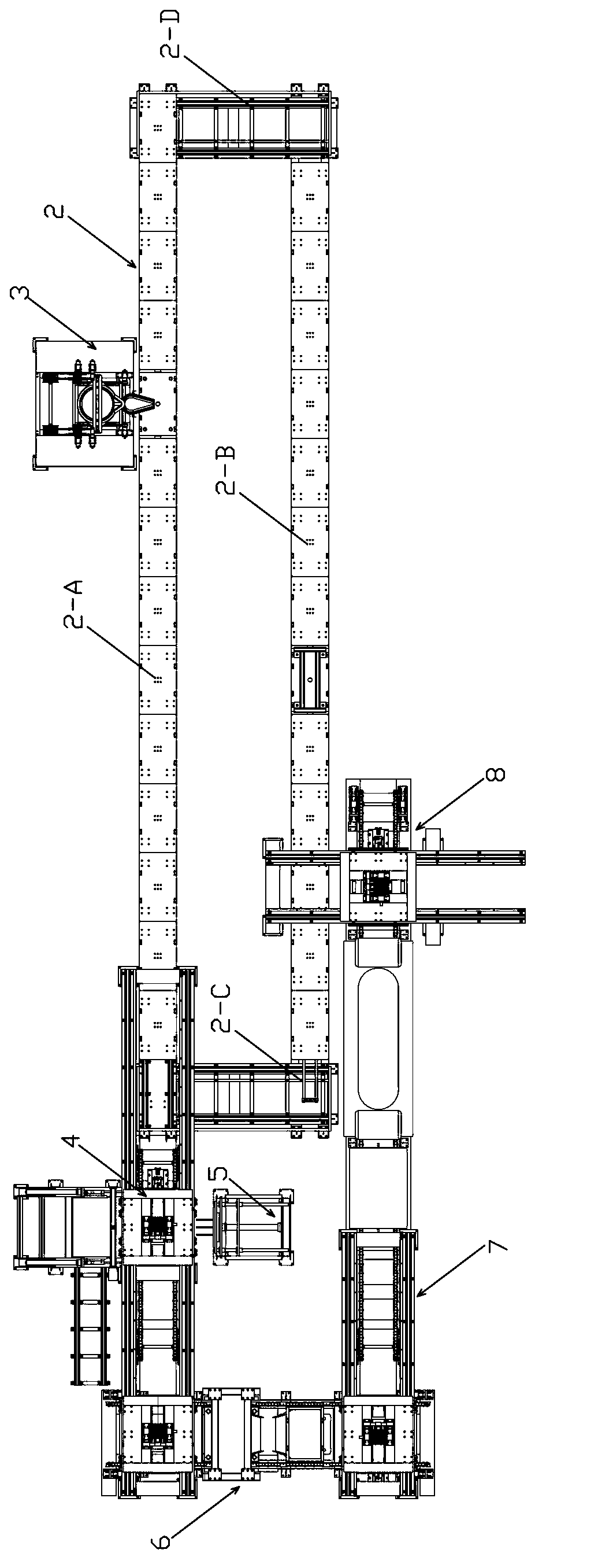
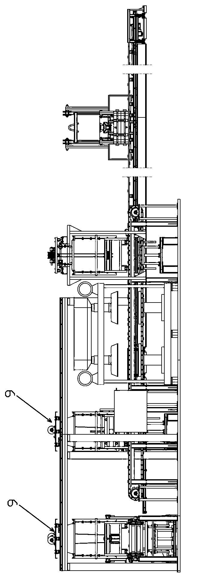
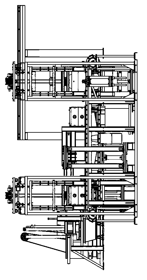
[0098] Embodiment 1: see Figure 1-3 The automatic sand casting system of this embodiment mainly includes the following parts: iron mold sand mold 1, combined rail 2, weighing casting device 3, parting mold turning device 4, mold turning and ejecting device 5, sand shaking device 6 , temperature control and sand injection molding device 7, turning box mold clamping device 8, gantry crane 9, combined track 2 includes casting light rail line 2-A (top) and mold clamping light rail line 2-B (bottom) arranged in parallel 2. Two horizontal light rail lines 2-C (left) and 2-D (right) are arranged in parallel for rail transition. The two horizontal light rail lines are respectively vertically connected to the casting light rail line 2-A (upper) and the mold-closing light rail line At both ends of 2-B (bottom), the four light rail lines are in a rectangular shape; one side of the casting light rail line is installed with a casting station, that is, a weighing casting device 3, and the ...

Embodiment 2

[0180] Embodiment 2: The difference between this embodiment and Embodiment 1 is that the weighing casting device of this embodiment is a slide rail type structure, that is, during the casting process, the sand box, that is, the iron mold sand mold, can not be moved, The sliding of the recasting device is used to adjust the positional relationship between it and the sand box.

[0181] see Figures 66-71 , the present embodiment does not have the support foot in embodiment 1, and a motor mounting plate 3-40 is fixedly installed under a steel bar of the base 3-1, and a walking motor 3-41 is fixedly installed on this mounting plate 3-40, walking The output shaft of the motor 3-41 is fixedly provided with a gear 3-42.

[0182] Two slide rails 3-43 are laid below the base 3-1, and the bottoms of the two slide rails 3-43 (along the length direction) are vertically fixedly connected with multiple concave steel bars 3-44, one of which is a slide rail 3-43 A tooth bar 3-45 is fixedly ...


PUM


Abstract

The invention discloses a sand-mould casting system, which comprises an iron type sand die and the like, wherein the iron mould sand die is combined by an upper die and a lower die to form a die cavity; an upper wall and a lower wall are respectively provided with a through hole communicated with the die cavity; a combined rail comprises a casting light rail, a die-compounding light rail and two parallel lateral light rails, wherein the casting light rail and the die-compounding light rail are in parallel; the two lateral light rails are respectively and vertically connected to two ends of the casting light rail and the die-compounding light rail; one side of the casting light rail is provided with a weighing and casting device; the iron mould sand die subjected to die compounding is arranged on the die-compounding light rail and enters the casting light rail after successively passing through the die-compounding light rail and one lateral light rail; the top of the through hole in the upper wall of the iron mould sand die just faces to the casting hole of the weighing and casting device; the casted iron mould sand die enters a die-splitting turnover device to separate the upper die from the lower die; one side of the die-splitting turnover device is provided with a die turnover ejection device used for ejecting out a workpiece in the die; then, the upper die and the lower die successively pass through a sand falling and vibrating device, a temperature control and sand ejecting and molding device and a turnover die-compounding device; and the turnover die-compounding device is positioned on one side of the die-compounding light rail.

Description

technical field [0001] The invention belongs to the technical field of casting, and in particular relates to an automatic sand casting system. Background technique [0002] Casting is a more economical blank forming method, especially for complex parts, it can show its economy. The size, shape, and weight of cast parts are applicable to a wide range. Therefore, in the machinery manufacturing industry, casting is the most important way to produce rough parts, and it is one of the very important basic links in the industrial chain of various machinery and equipment industries. . However, the casting production process will produce dust, harmful gases, noise, etc., which seriously affect the environment; in addition, the foundry industry is a labor-intensive industry with high labor intensity and low production efficiency. [0003] There are many casting methods, because this patent application mainly relates to sand casting technology, therefore, only describe the relevant b...

Claims


Application Information

Patent Timeline
Patent Type & Authority Applications(China)
IPC IPC(8): B22D46/00B22D47/02
Inventor 邹家春金碎娒王伟马新峰
Owner HANGZHOU HUNING ELEVATOR PARTS CO LTD
Why Eureka
Try Eureka