Concentric sleeve type five-layer coextrusion film blower handpiece

A co-extrusion blown film, sleeve-type technology, which is applied in the field of concentric sleeve-type five-layer co-extrusion blown film head, can solve problems such as loading and unloading, transportation troubles, processing machine tools that are incapable of processing tasks, and large pressure loss of molten materials.

Active Publication Date: 2013-04-03
GUANGDONG JINMING MACHINERY
View PDF6 Cites 12 Cited by
  • Summary
  • Abstract
  • Description
  • Claims
  • Application Information

AI Technical Summary

Problems solved by technology

[0009] 1. The machine head is very bulky and consumes a lot of alloy steel, which will undoubtedly increase the production cost (the production of film blowing machine heads requires special alloy steel, which is very expensive);
[0010] 2. The large size and heavy weight of the machine head make processing very difficult, and even make ordinary processing machine tools difficult to perform processing tasks;
[0011] 3. Loading, unloading, and transportation are troublesome, and ordinary cranes are incapable of lifting tasks;
[0012] 4. The size of the machine head is large, resulting in a long preheating time for the production of plastic film, and a large energy consumption in the production process;
[0013] 5. The large volume of the machine head means that the sealing interface area is large and the sealing is more difficult;
[0014] 6. The cross-section of the radial flow channel is small and the length of their continuous extension is large (the length of each radial flow channel exceeds 3 meters), and the flow channel with a small cross-section has a large pressure loss on the molten material, so it is necessary for the production of the machine head High extrusion pressure will

Method used


Image

  • Concentric sleeve type five-layer coextrusion film blower handpiece
  • Concentric sleeve type five-layer coextrusion film blower handpiece
  • Concentric sleeve type five-layer coextrusion film blower handpiece

Examples


Embodiment 1

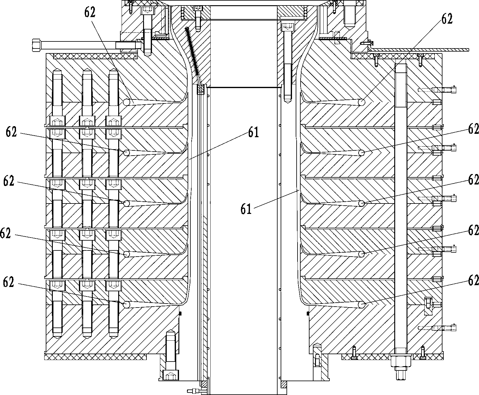
[0097] The concentric sleeve type five-layer co-extrusion film blowing head of this embodiment includes five sets of flow channel systems, each set of flow channel systems corresponds to guiding the flow of one layer of molten material before the film bubble is extruded; each set of flow channel systems It includes a layer of spiral flow channel on the upper part of the machine head and a general feeding port on the lower part of the machine head.

[0098] Image 6 , Figure 35 , Figure 36 As shown, the upper part of the machine head is provided with six concentric sleeves, each of which is nested inside and outside. The central axis of the machine head becomes the central axis m of the machine head; a layer of spiral flow channels is formed between the interface of two adjacent concentric sleeves, and the five layers of spiral flow channels are arranged in order from outside to inside according to the diameter, respectively. The spiral flow channel 57 , the second outer s...

Embodiment 2

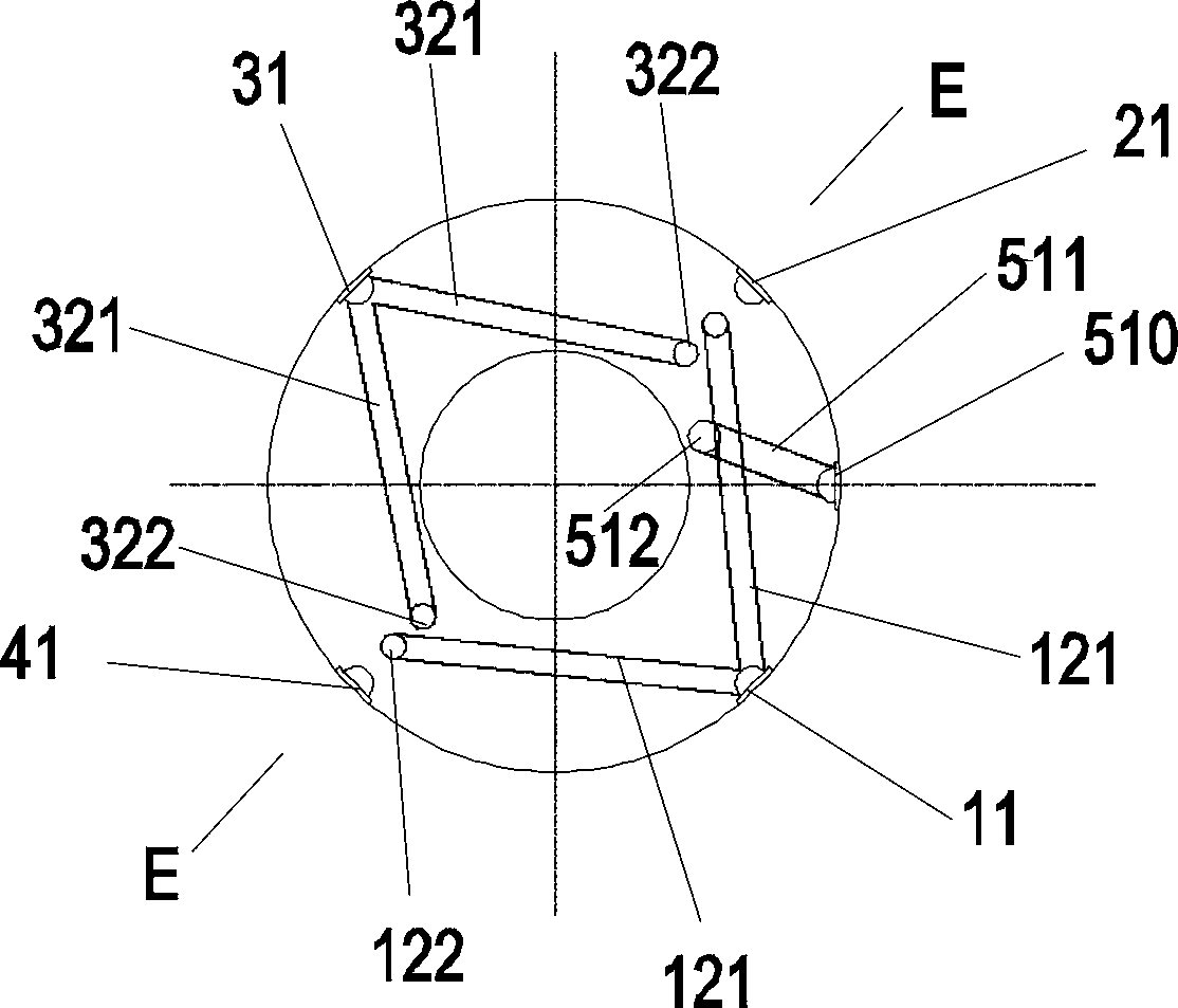
[0130] In the second embodiment, the vertical main flow channel 512 of the fifth set of flow channel system is staggered by an azimuth angle of 153° relative to the main feed inlet 11 of the first set of flow channel system, and the staggered direction is counterclockwise.

[0131] In this way, compared with Embodiment 1, the structures of the first runner system, the second runner system, and the fourth runner system of Embodiment 2 are exactly the same as those of Embodiment 1, while the fifth runner system of Embodiment 2 The runner system is staggered counterclockwise by 90° relative to the fifth runner system in the first embodiment.

[0132] In fact, the fifth set of flow channel system in Embodiment 2 starts from the horizontal sorting branch channel 543, and its downstream flow channels (including the horizontal sorting branch channel 543) are symmetrically the same with respect to the 90° rotation of the center of the machine head. Therefore, the second embodiment The...

Embodiment 3

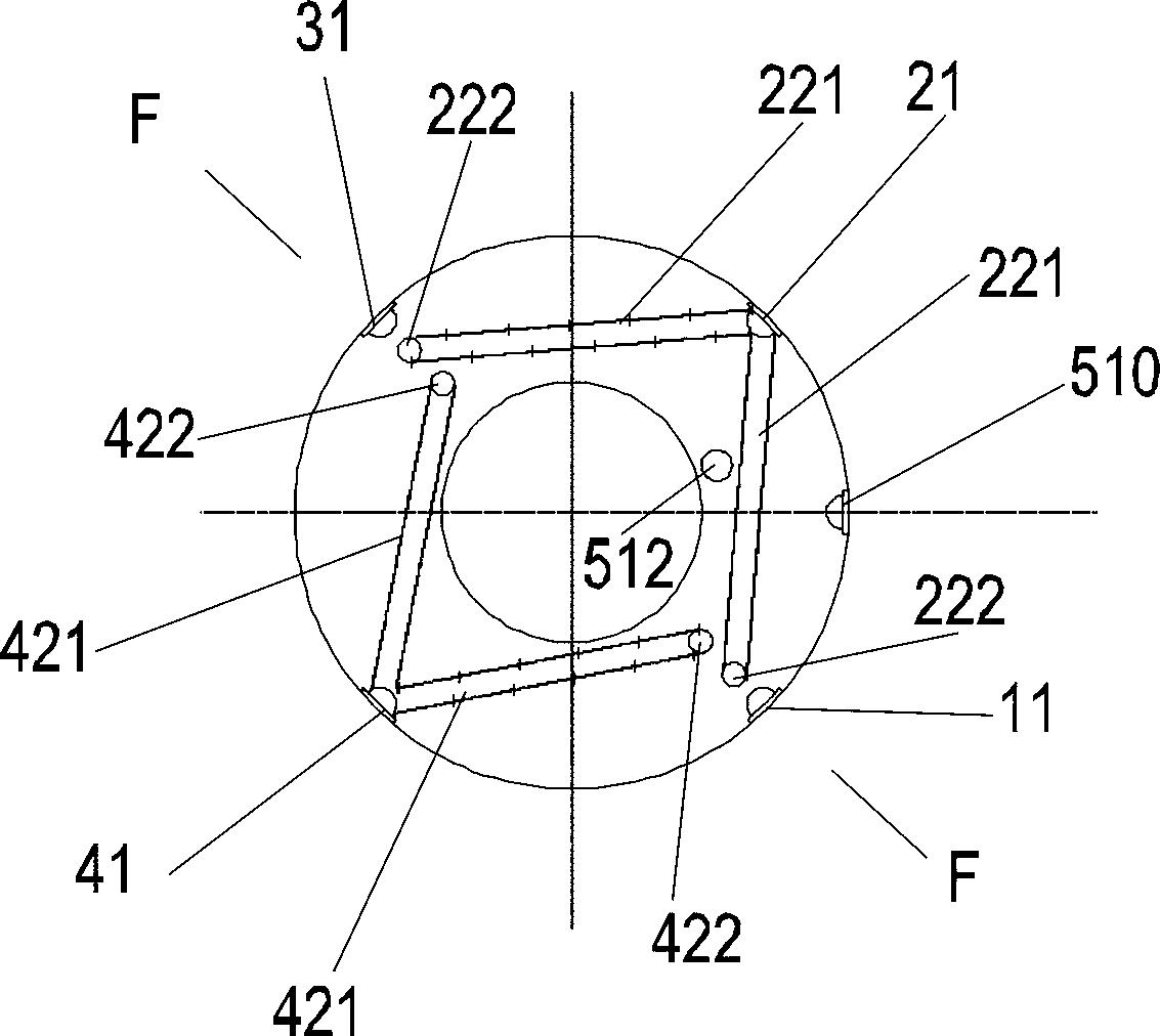
[0136] In the third embodiment, the vertical main flow channel 512 of the fifth set of flow channel system is staggered by an azimuth angle of 18° relative to the main feed port 11 of the first set of flow channel system, and the staggered direction is counterclockwise;

[0137] In this way, compared with Embodiment 1, the structures of the first runner system, the second runner system, and the fourth runner system of Embodiment 3 are exactly the same as those of Embodiment 1, while the fifth embodiment of Embodiment 3 The set of runner systems is staggered clockwise by 45° relative to the fifth set of runner systems in Embodiment 1, and the distribution of runners on the third interface is as follows: Figure 37 shown.

[0138] In fact, the fifth set of flow channel system in the third embodiment starts from the radial branch channel 544, and its downstream flow channels (including the radial branch channel 544) are symmetrical and the same with respect to the 45° rotation of...


PUM


Abstract

A concentric sleeve type five-layer coextrusion film blower handpiece comprises five sets of runner systems, wherein each set of runner system correspondingly guides one layer of fused material to flow, and comprises one layer of spiral runner at the upper part of the handpiece and a total feeding port at the lower part of the handpiece; four layers of distribution discs are arranged at the lower part of the handpiece, and consist of a bottom-layer distribution disc, a second-layer distribution disc, a third-layer distribution disc and a fourth-layer distribution disc; the tail end points of all forty horizontal arrangement branch runners in the five sets of runner systems are positioned on one circle of a third interface; the eccentric distances of the tail end points of the forty horizontal arrangement branch runners are all the same, and are more than those of vertical branch runners of the first set of runner system; the tail end points of eight horizontal arrangement branch runners in each set of runner system are evenly distributed in the peripheral direction; and the tail end points of two adjacent horizontal arrangement branch runners in one set of runner system are staggered from each other at a directional angle of 45 degrees. The handpiece can produce five-layer coextrusion plastic films with large breadths, and is small in size and convenient for processing.

Description

technical field [0001] The invention belongs to the technical field of plastic film blowing equipment, in particular to a concentric sleeve type five-layer co-extrusion film blowing head for producing five-layer co-extrusion plastic films. Background technique [0002] There are two main types of multi-layer co-extrusion blown film heads for producing plastic films. The first type is superimposed multi-layer co-extrusion blown film heads, and the second type is concentric sleeve multi-layer co-extrusion blown film heads. The structures of these two types of dies are very different, and the flow modes of molten materials are also very different during operation. [0003] The diameters of the ring-shaped die openings of each layer of materials in the superimposed multi-layer co-extrusion blown film head are the same, and the arrangement is in the form of superimposing up and down, and they are all located next to a ring-shaped vertical flow channel. When extruding, each layer...

Claims


Application Information

Patent Timeline
IPC IPC(8): B29C47/12B29C47/06B29C55/28B29C48/10B29C48/30
CPCB29C55/28B29C47/0054B29C47/705B29C47/12B29C47/065B29C47/0023B29C47/268B29C47/263B29C47/06B29C49/04B29C49/22B29L2009/00B29C48/08B29C48/09B29C48/10B29C48/0017B29C48/18B29C48/21B29C48/32B29C48/3363B29C48/338B29C48/705B29C49/04116
Inventor 马佳圳法兰克·卢布卡林楚漂
Owner GUANGDONG JINMING MACHINERY
Why Eureka
Try Eureka