Supercharge Your Innovation With Domain-Expert AI Agents!

Online annealing device and online annealing method for large-size optical fiber preform rod

A technology of optical fiber preform and annealing device, which is applied in manufacturing tools, glass manufacturing equipment, glass production, etc. It can solve the problems of high probability of fracture, uneven density of left and right taper parts and parallel parts, and easy cracks in the taper parts. Achieve the effects of reducing the probability of broken rods, avoiding the cracking of the cone, and uniform density of the cone

Active Publication Date: 2013-04-03
ZHONGTIAN TECH ADVANCED MATERIALS CO LTD +2
View PDF7 Cites 16 Cited by
  • Summary
  • Abstract
  • Description
  • Claims
  • Application Information

AI Technical Summary

Problems solved by technology

[0007]1. The deposition torch moves left and right to deposit SiO2 powder on the mandrel. When the deposition torch moves to both ends of the powder rod, it will The burning of the rod causes the rod to generate stress and reduce its strength. As the diameter of the powder rod increases, the weight of the powder preform increases, and the shear force on the rod increases. Therefore, the probability of breaking the rod during the deposition process is higher. Will have a certain impact on the pass rate;
[0008]2. The deposition torch completes the SiO2 powder attachment on the mandrel surface by moving back and forth from left to right. In this movement mode, the left and right cones are parallel to The burning time of the part will be the same, which will easily lead to the uneven density of the left and right cone parts and the parallel part. The deviation of the density during the deposition process will cause cracks, and the crack diffusion will cause the whole powder rod to crack and be scrapped.
[0015]In the existing large-size optical fiber preform OVD manufacturing technology, due to device and process reasons, there are defects in the design of the cone, and the probability of rod breakage and cracking is high
In addition, the cone powder is relatively fluffy, and the cone is prone to cracks when the powder rod is sintered
Moreover, due to the poor compactness of the sintered cone, the probability of breaking during the transportation of the rod is also very high
[0016]Raw materials, gas, electricity, etc. are the main components of the cost of preform rods. If the rods are broken or cracked near the end of deposition, it will directly lead to the scrapping of raw materials, etc., giving business losses

Method used


Image

  • Online annealing device and online annealing method for large-size optical fiber preform rod
  • Online annealing device and online annealing method for large-size optical fiber preform rod
  • Online annealing device and online annealing method for large-size optical fiber preform rod

Examples


Embodiment 1

[0078] The core rod was prepared by VAD technology, and after the core rod was extended, the refractive index profile was tested, and the required amount of the outer cladding was calculated from the test results.

[0079] The mandrel after the test is docked at both ends, and the mandrel is polished after the butt joint to remove the stress caused by the butt joint. The polished mandrel with the rod is called branch rod. According to the test results, the appropriate target weight is selected, and the OVD method is used to deposit the outer cladding on the mandrel, and finally a powder rod with a target outer diameter of 150mm is obtained.

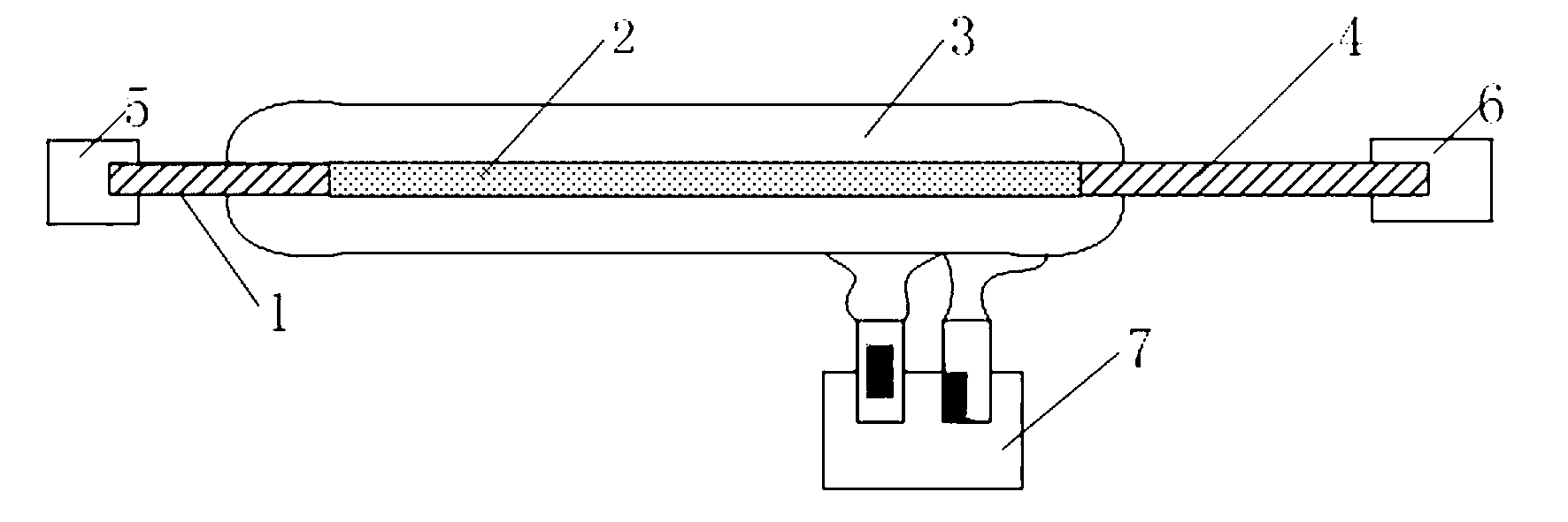
[0080] The deposition equipment is not equipped with an online annealing device. After the deposition is completed, the adhesion force of the cone of the powder rod is tested to check the force required for the powder peeling off of the cone.

[0081] Observe the condition of the cone of the preform after the sintering test to see if ther...

Embodiment 2

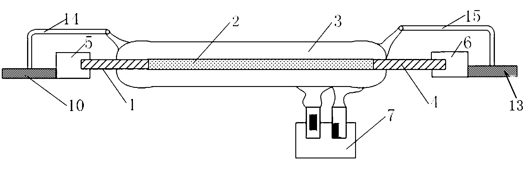
[0084] The deposition equipment is equipped with a fixed online annealing device, and the other processes are the same as those in Example 1.

[0085] After the deposition is complete, the cone adhesion of the powder rod is tested to verify the force required for the powder to peel off the cone.

[0086] Observe the condition of the cone of the preform after the sintering test to see if there are abnormalities such as cracking and peeling.

[0087] The deposition ends normally, the powder in the cone part does not peel off, and the preform with a normal cone part after sintering is judged as qualified, and the subsequent process is carried out.

Embodiment 3

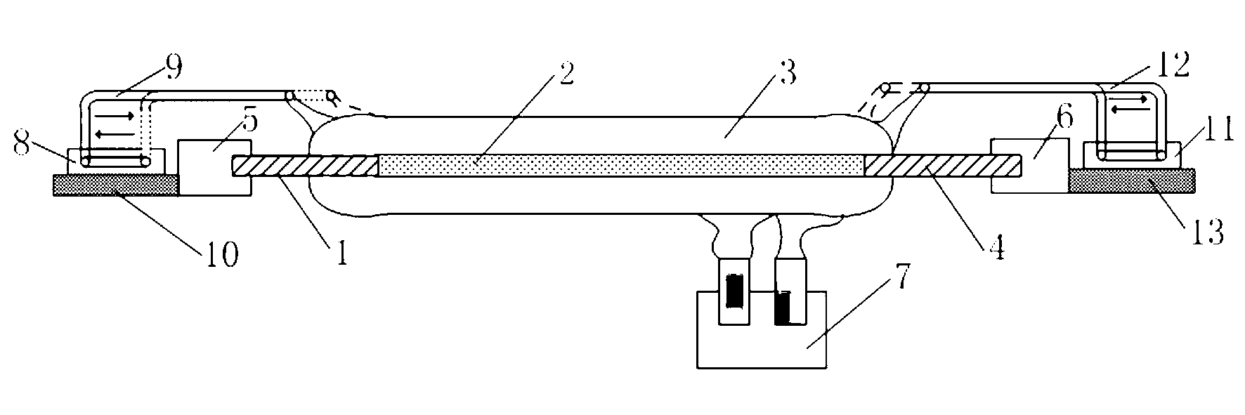
[0089] The deposition equipment is equipped with the mobile on-line annealing device of the present invention, and the other processes are the same as those in Embodiment 1.

[0090] After the deposition is complete, the cone adhesion of the powder rod is tested to verify the force required for the powder to peel off the cone.

[0091] Observe the condition of the cone of the preform after the sintering test to see if there are abnormalities such as cracking and peeling.

[0092] The deposition ends normally, the powder in the cone part does not peel off, and the preform with a normal cone part after sintering is judged as qualified, and the subsequent process is carried out.

[0093] The main technical process of the present invention will be described in detail below in conjunction with the drawings.

[0094] 1. The composition of the online annealing device

[0095] 1) The cylinder that controls the movement of the annealing device;

[0096] 2) Round metal blowtorch: about...


PUM


Abstract

The invention discloses a mobile online annealing device and an online annealing method in process of manufacturing the large-size optical fiber preform rod, which are used for eliminating the stress generated due to flame burning of a blast lamp in the sedimentation process of an outsourcing layer of the optical fiber preform rod, and further improving the quality of the perform rod. The online annealing device comprises fixed bases I and II, cylinders I and II, metal blast lamps I and II, a gas flow controller, a metal gas pipe and a Teflon pipeline, wherein the fixed bases I and II are respectively matched with chuck substrates I and II, the metal blast lamp I is connected with the cylinder I, and the metal blast lamp II is connected with the cylinder II; the cylinders I and II are respectively arranged on the fixed bases I and II so as to position the metal blast lamp I and II; the metal blast lamp I and II are connected with the metal gas pipe by the Teflon pipeline; and the gas flow controller is arranged on the metal gas pipe.

Description

technical field [0001] An on-line annealing device and an on-line annealing method for a large-size optical fiber preform in the present invention relate to a mobile on-line annealing device and a method thereof in the manufacturing process of a large-size optical fiber preform, which are used to eliminate the outer cladding deposition of the optical fiber preform During the process, due to the stress generated by the burning of the blowtorch flame, the quality of the preform is improved and the production efficiency is increased. Background technique [0002] In order to reduce the cost of optical fiber production and improve deposition efficiency, large-size optical fiber preforms have become the main direction of preform technology development. [0003] There are four main methods of producing silica optical fiber prefabricated core rods: [0004] Microwave plasma activated chemical vapor deposition (PCVD- Plasma activated Chemical Vapor Deposition), modified chemical va...

Claims


Application Information

Patent Timeline
IPC IPC(8): C03B37/018C03B25/00
CPCC03B37/01486C03B37/0148C03B37/0142Y02P40/57
Inventor 谢康张彬钱宜刚陈京京沈一春薛济萍
Owner ZHONGTIAN TECH ADVANCED MATERIALS CO LTD
Features
  • R&D
  • Intellectual Property
  • Life Sciences
  • Materials
  • Tech Scout
  • Unparalleled Data Quality
  • Higher Quality Content
  • 60% Fewer Hallucinations
Learn More