Directly-connected headstock gear

A hoist, direct-connected technology, applied in the field of hoists, can solve the problems of complex structure of hoists and long power transmission process, etc.

Active Publication Date: 2013-04-03
江苏武东机械有限公司
View PDF6 Cites 11 Cited by
  • Summary
  • Abstract
  • Description
  • Claims
  • Application Information

AI Technical Summary

Problems solved by technology

Therefore, the entire power transmission process is relatively long, and the structure of the corresponding hoist is also relatively complicated.
[0006] And for the above-mentioned first patent document, although its invention name is direct-couple

Method used


Image

  • Directly-connected headstock gear
  • Directly-connected headstock gear
  • Directly-connected headstock gear

Examples


Embodiment 1

[0071] (Example 1, direct-connected single suspension point suspension hoist)

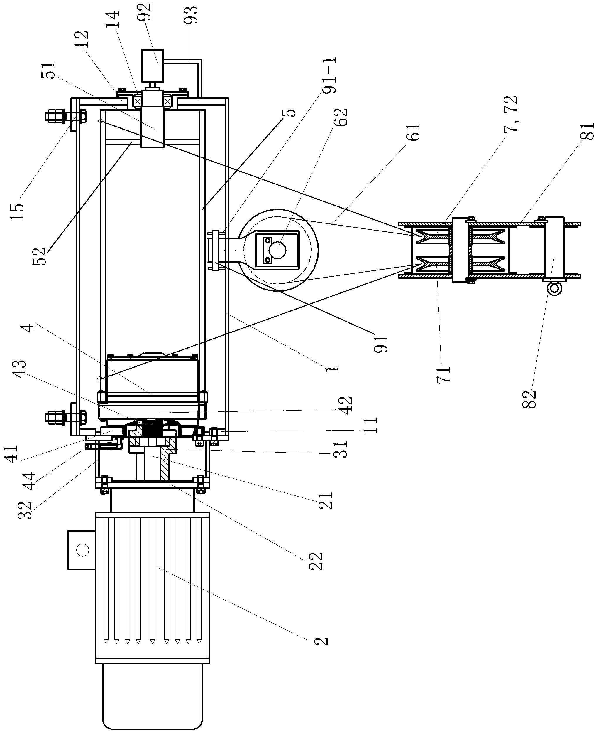
[0072] See figure 1 , the direct-connected hoist of this embodiment is a direct-connected single-suspension-point hoist, specifically a direct-connected single-suspended-point hoist.

[0073] The direct-coupled single-suspension suspension hoist of this embodiment includes a frame 1, a motor 2, a coupling 31, a connecting seat 32, a reducer 4, a wire rope reel 5, a wire rope 61, a balance pulley device 62, and a movable pulley block 7. Spreader 8, lifting capacity limiter 91 and height indicator device 92; motor 2 is fixed on frame 1 through connection seat 32, motor 2 is connected with input shaft of reducer 4 through coupling 31, reducer 4 One end of it is fixed on the frame 1, and the other end is positioned at the inside of the wire rope reel 5. The rotating shaft of motor 2, shaft coupling 31, input shaft and output end of speed reducer 4 and wire rope reel 5 are coaxially arranged.

[0074...

Embodiment 2

[0095] (Example 2, direct-connected single suspension point suspension hoist)

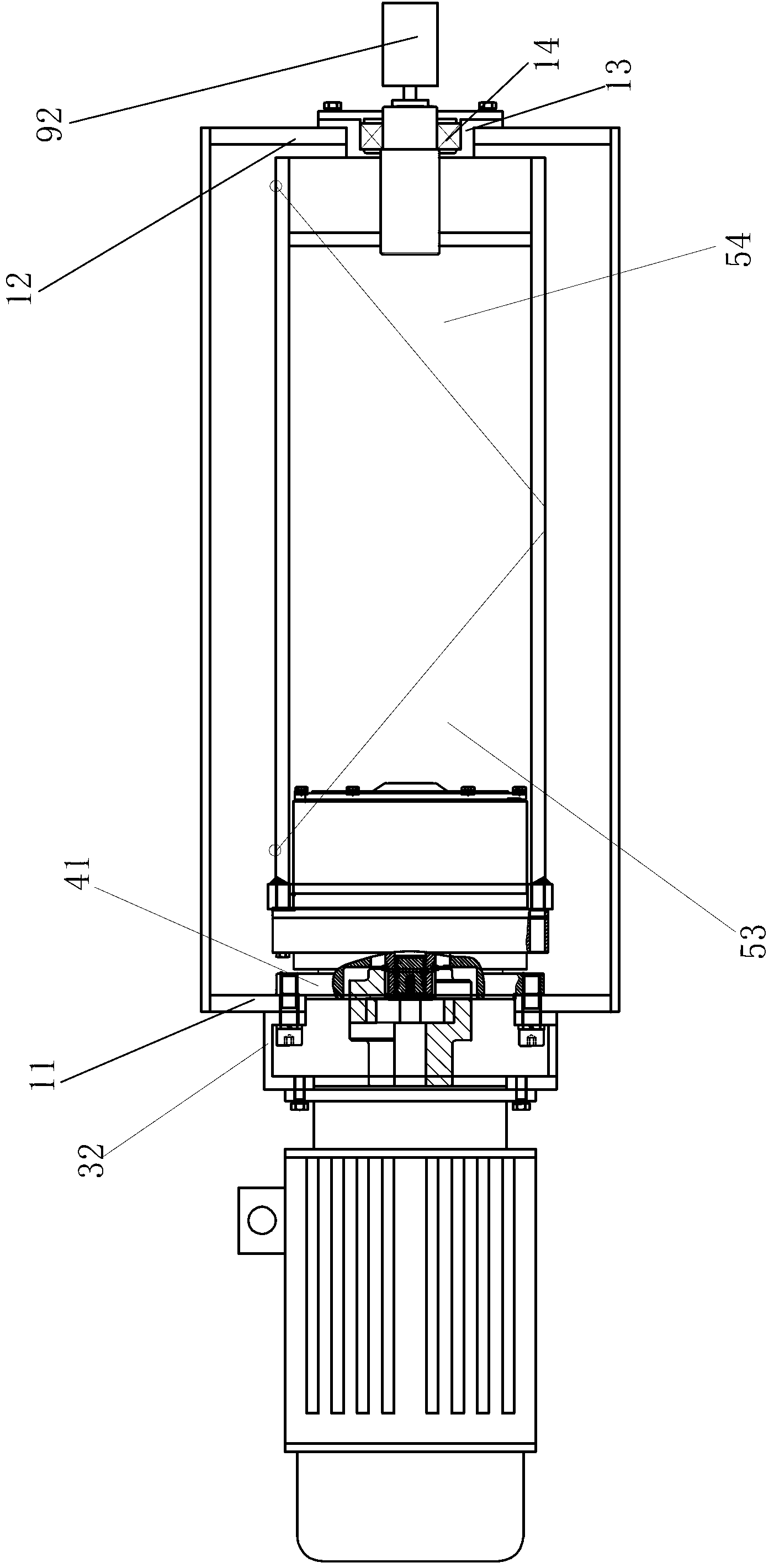
[0096] See figure 2 , the rest of the direct-coupled single-point hoist hoist of this embodiment is the same as that of Embodiment 1, the difference is that: the center of the right connecting plate of the connecting seat 32 is provided with a through hole, and the periphery of the through hole is provided with a circle of mounting holes; The edge of the left end face of the right connecting plate is welded and fixed to the right end face of the connecting ring, so that the left end face of the right connecting plate is located inside the connecting ring.

[0097] The right connecting plate of the connecting seat 32 is located in the center of the left end face of the left end plate 11 of the frame 1, and is in contact with the left end face of the left end plate 11 of the frame 1 from left to right; the fixed flange 41 of the reducer 4 is located at The center of the right side end face of left ...

Embodiment 3

[0098] (Embodiment 3, Direct-connected single hoisting point bottom mounted hoist)

[0099] See Figure 4 , the direct-connected single-suspension hoist of this embodiment is a direct-connected single-suspension bottom-mounted hoist, and the rest of the hoist is the same as that of Embodiment 1, except that the installation hole of the frame 1 is set at the lower connection On the frame, the lower connecting frame of the frame 1 is provided with a lower mounting hole 16, and the frame 1 can be fixed on the mounting platform of the dam through the lower mounting hole 16 during use.


PUM


Abstract

The invention discloses a directly-connected headstock gear. The speed reducer of the directly-connected headstock gear is a planetary gear speed reducer. The planetary gear speed reducer comprises a fixed flange, a movable flange and an input shaft, wherein the fixed flange of the speed reducer is fixed on a machine frame; the movable flange is fixedly connected with the end of the cylinder of a wire rope reel; the structure part, on one side of the movable flange, of the speed reducer is positioned in the wire rope reel; an electric motor is connected with the input shaft of the speed reducer through a shaft coupling; after the speed is reduced by a speed reducing mechanism of a speed reducer, a torque is output by the movable flange; and the movable flange drives the steel rope reel which is fixedly connected with the movable flange to rotate. The speed reducer and the wire rope reel are not required to be driven by an exposed gear but are connected with each other directly, so that the directly-connected headstock gear provided by the invention is realized. The width of the headstock gear can be reduced by 50 percent; the weight can be reduced by 50 percent; the overall structure is simple; the occupied space is small; the civil engineering quantity is reduced; and moreover, the directly-connected headstock gear is convenient in maintenance and has attractive appearance.

Description

technical field [0001] The invention relates to a hoist in water conservancy and hydropower projects, in particular to a direct-connected hoist. Background technique [0002] The hoist is widely used in various large-scale water supply and drainage, water conservancy and hydropower projects, and the purpose of opening and closing the gates is achieved by controlling the lifting of various gates. At present, the setting of flood gates in water conservancy and hydropower projects is limited by factors such as water level and hub layout, and the layout of direct-lift plane gates and straight-pull winch hoists is often used. However, the size of the existing hoist or frame is large and heavy, so the cost is relatively high, and the installation and maintenance of the hoist is relatively difficult; moreover, the amount of civil engineering required to match the hoist is also large, which brings difficulty in construction High, long construction period, poor overall seismic resis...

Claims


Application Information

Patent Timeline
IPC IPC(8): E02B7/36
Inventor 钟晓东钟鲁江
Owner 江苏武东机械有限公司
Why Eureka
Try Eureka