Novel large torque piling machine power head hardened reducer

A hard-tooth surface reducer and high-torque technology, which is applied in the direction of mechanical equipment, transmission devices, transmission device parts, etc., can solve problems that affect normal use and service life, centrifugal force cannot cancel each other, and affect the performance of pile drivers, etc., to achieve Eliminate running influence, improve smooth running performance, and reduce noise

Inactive Publication Date: 2013-04-03
JIANGSU TAILAI REDUCER
View PDF5 Cites 45 Cited by
  • Summary
  • Abstract
  • Description
  • Claims
  • Application Information

AI Technical Summary

Problems solved by technology

The power head of the pile driver generally uses a three-ring reducer to output power. Its double crankshaft is connected to three tooth plates. The phase difference of the three eccentric sections of the crankshaft is 120°. The three tooth plates are respectively installed on the three eccentric sections of the crankshaft. The centrifugal force generated by the three tooth plates cannot cancel each other out during operation. When the power head is running at high speed, the centrifugal force increases, which increases the adverse effects of manufacturing and processing deviations, resulting in increased vibration, increased noise, and high oil temperature. At the same time, the bearing load Increase the size, increase the wear, affect the performance of the pile driver, and shorten the service life
If it encounters complex strata such as quicksand, pebbles, and strongly weathered rocks, it will further affect its normal use and service life

Method used


Image

  • Novel large torque piling machine power head hardened reducer

Examples


Embodiment Construction

[0014] The present invention will be further described below in conjunction with drawings and embodiments.

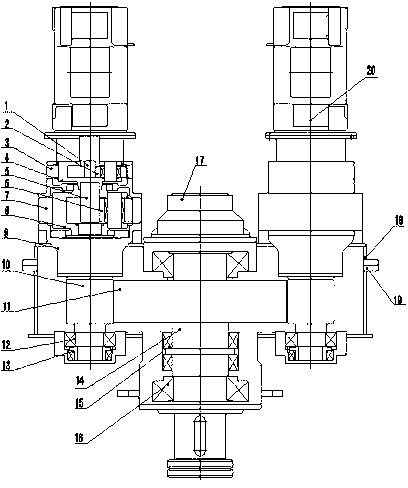
[0015] figure 1 As shown, a new type of high-torque pile machine power head hard tooth surface reducer includes a first-stage sun gear 1, a first-pole planetary gear 2, a first-stage outer ring gear 3, a first-stage planet carrier 4, a first-stage sun gear 5, and a first-stage sun gear. Pole planetary gear 6, stage outer ring gear 7, secondary planet carrier 8, planetary support body 9, helical gear shaft 10, sun gear 11, first roller bearing 12, first plane bearing 13, output shaft 14, second Plane bearing 15 , second roller bearing 16 , grouting device system 17 , body 18 , cover 19 and input motor 20 . The two ends of the output shaft 14 are connected and supported on the machine body 18 and the cover body 19 respectively. The output shaft 14 on one side of the machine body 18 is connected to the grouting device system 17, and the central gear 11 is connected to the...


PUM


Abstract

The invention relates to a novel large torque piling machine power head hardened reducer. The reducer comprises an engine body, a cover body, a central gear, an output shaft and more than two groups of planetary transmission mechanisms, wherein two ends of the output shaft are respectively supported on the engine body and the cover body in a penetrating manner; the output shaft at one side of the engine body is in end connection with a grouting device system; the central gear is connected onto the output shaft in a penetrating manner and is arranged between the engine body and the cover body; the more than two groups of planetary transmission mechanisms are supported on the engine body by taking the output shaft as a symmetric center; the planetary transmission mechanism comprises an input motor, and first-stage and second-stage planetary transmission mechanisms; the input motor is connected to an inclined gear shaft which is arranged in the engine body and the cover body through the first-stage and second-stage planetary transmission mechanisms; and the inclined gear shaft is meshed with the central gear. By adopting the more than two groups of planetary transmission mechanisms, the running power of the reducer is shunted; the reducer can stably and safely run for a long time under the large torque in matched with the meshed inclined gear shaft and the output shaft through the combination supporting of a roller bearing and a plane bearing; and the reducer has the advantages of compact structure, stable running, shunted work load, little equipment abrasion, low noise and long service life.

Description

technical field [0001] The invention relates to a speed reducer, in particular to a novel high-torque pile driver power head hard tooth surface speed reducer. Background technique [0002] In building construction, the working efficiency of pile driver equipment depends on the rotation speed of the auger. If the rotation speed is appropriate, the piling depth per unit time will be improved. The power head of the pile driver generally uses a three-ring reducer to output power. Its double crankshaft is connected to three tooth plates. The phase difference of the three eccentric sections of the crankshaft is 120°. The three tooth plates are respectively installed on the three eccentric sections of the crankshaft. The centrifugal forces generated by the three tooth plates cannot cancel each other out during operation. When the power head is running at high speed, the centrifugal force increases, which increases the adverse effects of manufacturing and processing deviations, resu...

Claims


Application Information

Patent Timeline
Patent Type & Authority Applications(China)
IPC IPC(8): F16H1/46F16H57/023F16H57/021E02D15/04
Inventor 殷凡张吉林丁锁平戴红杨玲杨天益
Owner JIANGSU TAILAI REDUCER
Why Eureka
Try Eureka