Heat exchange system

A heat exchange system and vacuum heat insulation technology, applied in the field of heat exchange systems, can solve the problems of reduced service life of refrigeration equipment, decreased energy efficiency of refrigeration equipment, frequent start and stop of refrigeration equipment, etc., to reduce insulation costs, reduce temperature differences, and improve storage capacity. the effect of the effect

Active Publication Date: 2015-04-15
江苏恒安储能科技有限公司
View PDF9 Cites 0 Cited by
  • Summary
  • Abstract
  • Description
  • Claims
  • Application Information

AI Technical Summary

Problems solved by technology

[0002] In the traditional structure, the heat exchange system generally requires refrigeration equipment to generate cooling capacity, such as using a compressor for refrigeration, and then transporting the cooling capacity by pumps and other transportation equipment, and the cooled device often has excess energy that is wasted
During the use of cooling capacity, the cooling capacity is generally produced in real time according to the working conditions. Under certain working conditions, the refrigeration equipment may start and stop frequently, resulting in a decrease in the energy efficiency of the refrigeration equipment and reducing the service life of the refrigeration equipment.

Method used


Image

  • Heat exchange system
  • Heat exchange system
  • Heat exchange system

Examples


Embodiment 1

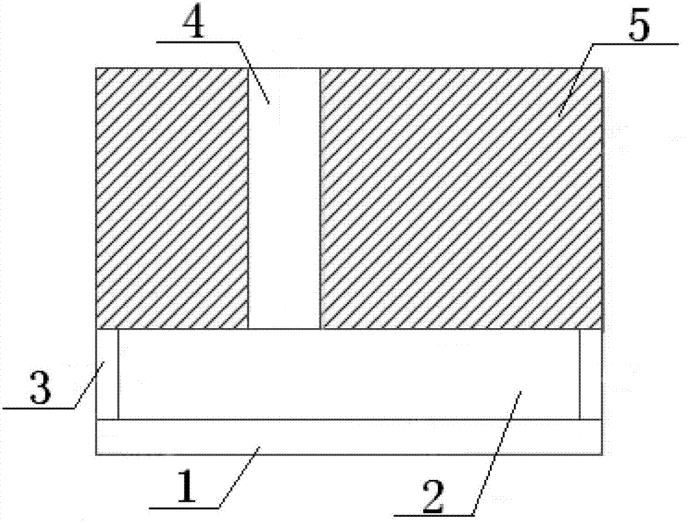
[0022] Embodiment 1 of the present invention: as figure 1 As shown, a heat exchange system includes a refrigeration layer 1, a cold storage layer 2, a cooling channel 4 and a cooled device 5, the refrigeration layer 1 and the cold storage layer 2 are arranged below the cooled device 5, and the cold storage layer 2 is set Above the cooling layer 1 , an insulating layer 3 is provided on the outside of the cold storage layer 2 .

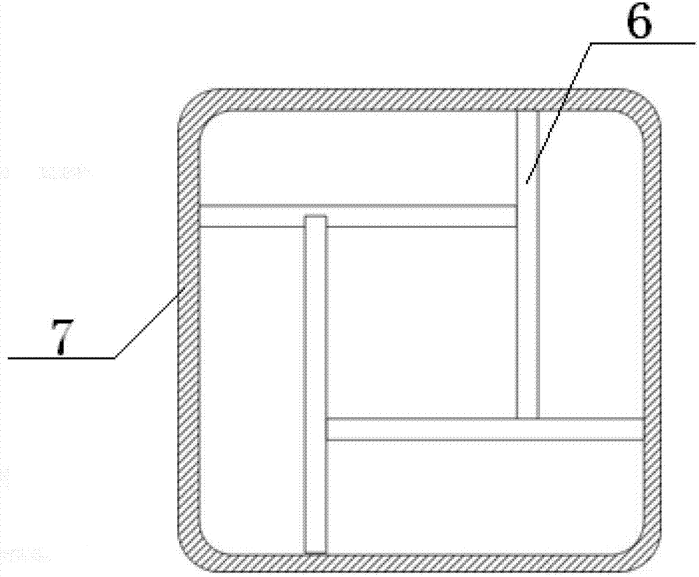
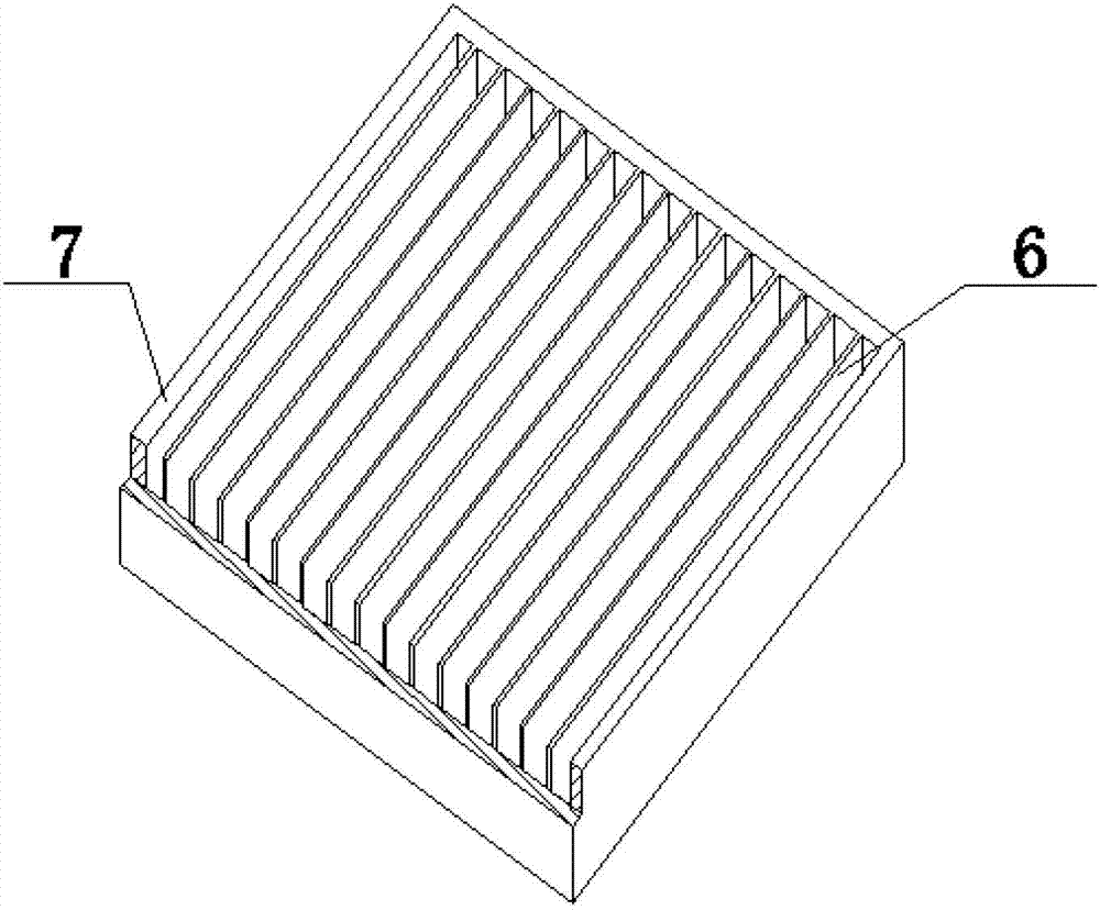
[0023] Such as figure 2 As shown, the connection between the cooling channel 4 and the cooled device 5 is provided with a heat exchange tube wall 7; inside the cooling channel 4 there are also 10 cooling fins 6.

[0024] The cold storage layer 2 adopts phase change cold storage; the phase change cold storage adopts ice storage.

[0025] The heat insulation layer 3 adopts a vacuum heat insulation layer.

[0026] The energy supply of the cooling layer 1 comes from the residual energy of the cooled device 5 .

[0027] The heat sink 6 is also provided...

Embodiment 2

[0028] Embodiment 2 of the present invention: as figure 1 As shown, a heat exchange system includes a refrigeration layer 1, a cold storage layer 2, a cooling channel 4 and a cooled device 5, the refrigeration layer 1 and the cold storage layer 2 are arranged below the cooled device 5, and the cold storage layer 2 is set Above the cooling layer 1 , an insulating layer 3 is provided on the outside of the cold storage layer 2 .

[0029] Such as figure 2 As shown, the connection between the cooling channel 4 and the cooled device 5 is provided with a heat exchange tube wall 7 ; inside the cooling channel 4 there are also 100 cooling fins 6 .

[0030] The cold storage layer 2 adopts phase change cold storage; the phase change cold storage adopts ice storage.

[0031] The heat insulation layer 3 adopts a vacuum heat insulation layer.

[0032] The energy supply of the cooling layer 1 comes from the residual energy of the cooled device 5 .

[0033] The heat sink 6 is also provi...

Embodiment 3

[0034] Embodiment 3 of the present invention: as figure 1 As shown, a heat exchange system includes a refrigeration layer 1, a cold storage layer 2, a cooling channel 4 and a cooled device 5, the refrigeration layer 1 and the cold storage layer 2 are arranged below the cooled device 5, and the cold storage layer 2 is set Above the cooling layer 1 , an insulating layer 3 is provided on the outside of the cold storage layer 2 .

[0035] Such as figure 2 As shown, the connection between the cooling channel 4 and the cooled device 5 is provided with a heat exchange tube wall 7; inside the cooling channel 4 there are also 1000 cooling fins 6.

[0036] The cold storage layer 2 adopts phase change cold storage; the phase change cold storage adopts ice storage.

[0037] The heat insulation layer 3 adopts a vacuum heat insulation layer.

[0038] The energy supply of the cooling layer 1 comes from the residual energy of the cooled device 5 .

[0039] The heat sink 6 is also provid...


PUM


Abstract

The invention discloses a heat exchange system, comprising a refrigeration layer (1), a cold storage layer (2), a cooling channel (4) and a device (5) to be cooled, wherein the refrigeration layer (1) and the cold storage layer (2) are both arranged below the device (5) to be cooled, the cold storage layer (2) is arranged above the refrigeration layer (1), the outer side of the cold storage layer (2) is provided with a heat-insulation layer (3), and the cooling channel (4) is arranged in the device (5) to be cooled and is connected with the cold storage layer (2). According to the invention, the remained energy of the heat exchange system per se is used as energy to be consumed for refrigeration, an airflow is generated by virtue of the effect that gas is heated to expand and rise, so that conveying equipment is omitted, the consumed electric energy is reduced greatly, and the cold storage layer is arranged so that refrigeration equipment is unnecessary to start and stop frequently and thus is prolonged in service life.

Description

technical field [0001] The invention belongs to the field of heat dissipation, and in particular relates to a heat exchange system. Background technique [0002] In the traditional structure, the heat exchange system generally requires refrigeration equipment to generate cold energy, such as using a compressor to refrigerate, and then pumps and other conveying equipment to deliver the cold energy, and the excess energy of the cooled device is often wasted. During the use of cooling capacity, the cooling capacity is generally produced in real time according to the working conditions. Under certain working conditions, the refrigeration equipment may start and stop frequently, resulting in a decrease in the energy efficiency of the refrigeration equipment and a reduction in the service life of the refrigeration equipment. Contents of the invention [0003] The purpose of the present invention is to provide a heat exchange system, which uses its own surplus energy as cooling e...

Claims


Application Information

Patent Timeline
Patent Type & Authority Patents(China)
IPC IPC(8): F28D15/00H01M8/04007
CPCY02E60/50
Inventor 张祺孟琳刘学军陆克
Owner 江苏恒安储能科技有限公司
Why Eureka
Try Eureka