Activation circuit tester

A technology for activating circuits and testers, which can be used in weapon accessories, guidance methods, offensive equipment, etc. It can solve the problems that the tester cannot test the high current, and achieve the effects of convenient and fast testing, safe testing, and avoiding overcurrent phenomena

Active Publication Date: 2015-05-06
BEIJING INST OF ELECTRONICS SYST ENG
View PDF5 Cites 0 Cited by
  • Summary
  • Abstract
  • Description
  • Claims
  • Application Information

AI Technical Summary

Problems solved by technology

[0006] The purpose of the present invention is to solve the problem that conventional test instruments cannot perform large current tests in a short time, that is, to test the load capacity of the ignition control power supply, and provide an activation circuit tester

Method used


Image

  • Activation circuit tester
  • Activation circuit tester
  • Activation circuit tester

Examples


specific Embodiment approach 1

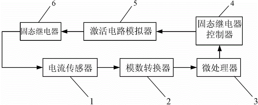
[0020] Specific implementation mode one: the following combination figure 1 Describe this embodiment, the activation circuit tester described in this embodiment, the tester includes a current sensor 1, an analog-to-digital converter 2, a microprocessor 3, a solid state relay controller 4, an activation circuit simulator 5 and a solid state relay 6 ;

[0021] The current sensor 1 collects the current in the activation current loop in the activation circuit, and sends the current signal to the analog signal input terminal of the analog-to-digital converter 2; the digital signal output terminal of the analog-to-digital converter 2 and the current detection of the microprocessor 3 The signal input terminal is connected; the relay control signal output terminal of the microprocessor 3 is connected with the relay control signal input terminal of the solid state relay controller 4; the circuit control signal output terminal of the solid state relay controller 4 is connected with the ...

specific Embodiment approach 2

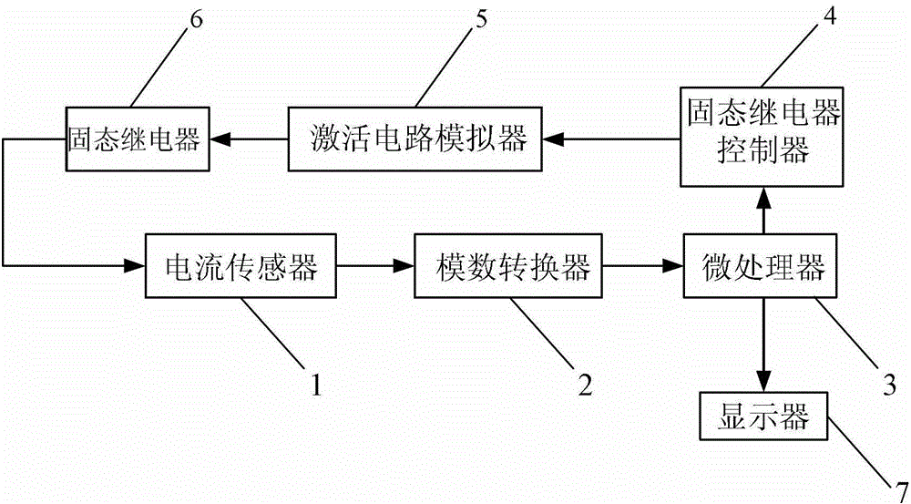
[0024] Specific implementation mode two: the following combination figure 2 Describe this embodiment mode, this embodiment mode is a further description to Embodiment 1, the difference between this embodiment mode and Embodiment 1 is that the tester also includes a display 7; the display signal output terminal of the microprocessor 3 is connected to the display 7 display signal input.

specific Embodiment approach 3

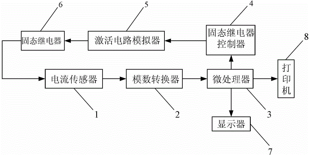
[0025] Specific implementation mode three: the following combination image 3 Describe this embodiment, this embodiment is a further description of Embodiment 1 or 2, the difference between this embodiment and Embodiment 1 or 2 is that the tester also includes a printer 8; the print signal of the microprocessor 3 The output end is connected to the print signal input end of the printer 8 .

[0026] working principle:

[0027] After power-on, the multi-channel acquisition circuit will work at the same time. Taking the first channel as an example, the microprocessor 3 outputs a high level, which makes the output terminal of the solid-state relay controller 4 conduct, so that the activation circuit is in the conduction state. At the same time, the microprocessor 3 is in a cyclic detection state for the voltage input to the microprocessor. When the switch of the 28V battery to be tested is turned on, the current flows through the resistor, the solid state relay controller 4 and th...


PUM


Abstract

The invention relates to an activation circuit tester, which aims to solve the problem that the common tester can not be used for carrying out a big-current test within a short time, i.e. the load capability of an emission control ignition power. A current sensor collects current in an activation current loop in the activation circuit; a current signal is sent to the analog signal input end of an analog-digital converter; the digital signal output end of the analog-digital converter is connected with the current detection signal input end of a microprocessor; the relay control signal output end of the microprocessor is connected with the relay control signal input end of a solid relay controller; the circuit control signal output end of the solid relay controller is connected with the circuit control signal output end of an activation circuit simulator; the switching control signal output end of the activation circuit simulator is connected with the switching control signal input end of the solid relay controller; and the switch of the solid relay controller is connected into the activation current loop in series. The activation circuit tester can be used for multiple types of emission control butt joint for realizing emission control function tests and power supply performance tests.

Description

technical field [0001] The present invention relates to active circuit testers. Background technique [0002] As an important part of the weapon system, the launch control system's most critical function is to implement safe and reliable launch control to ensure the effective interception of the target by the weapon system. [0003] The most critical technical link in the launch process is the launch sequence control. Due to the rapid response requirements of the weapon system, the launch sequence generally adopts the irreversible sequence control mode. The content and logic of the control sequence are relatively complicated. The launch sequence control can be completed in a relatively short period of time. In this process, the launch control system must not only complete multi-channel battery activation control, voltage detection control, power transfer control, parameter binding, verification and start-up flight control, etc. The ignition control of the main and auxiliary...

Claims


Application Information

Patent Timeline
Patent Type & Authority Patents(China)
IPC IPC(8): F41G3/32
Inventor 罗南斌贾军强张润东
Owner BEIJING INST OF ELECTRONICS SYST ENG
Why Eureka
Try Eureka