Synthetic aperture laser imaging radar large-visual-field heterodyne detection device

A technology of synthetic aperture laser and imaging radar, which can be used in measurement devices, radio wave measurement systems, instruments, etc., and can solve problems such as small field of view

Active Publication Date: 2013-04-03
SHANGHAI INST OF OPTICS & FINE MECHANICS CHINESE ACAD OF SCI
View PDF2 Cites 20 Cited by
  • Summary
  • Abstract
  • Description
  • Claims
  • Application Information

AI Technical Summary

Problems solved by technology

[0004] Prior Art [5] (Yan Aimin, Liu Liren, Zhou Yu, Sun Jianfeng. General synthetic aperture imaging laser radar optical antenna, utility model patent, application number: 200920066851.0) proposed a general synthetic aperture imaging laser radar radar optical antenna structure , which realizes the laser emission with secondary phase additional bias and the defocused optical reception that eliminates the wavefront difference of the echo signal. It can be used in far-field or near-field situations, and the emission wavefront and receiving field of view can be adjusted by controlling the corresponding aperture size, but this The device, the transmitting telescope and the receiving telescope are assembled together through a common main telescope, and the transmitting and receiving must be carried out in time-sharing, and the maximum field of view is only determined by the diffraction of the optical antenna aperture, and the field of view is small

Method used


Image

  • Synthetic aperture laser imaging radar large-visual-field heterodyne detection device
  • Synthetic aperture laser imaging radar large-visual-field heterodyne detection device
  • Synthetic aperture laser imaging radar large-visual-field heterodyne detection device

Examples


Embodiment Construction

[0059] The present invention will be described in further detail below in conjunction with the embodiments and accompanying drawings, but the protection scope of the present invention should not be limited thereby.

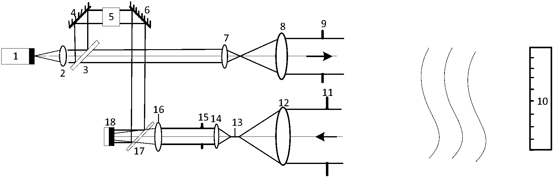
[0060] see first figure 1 , figure 1 It is a structural schematic diagram of a large-field-of-view heterodyne detection device for a synthetic aperture laser imaging radar of the present invention. figure 1 It is also a system diagram of an embodiment of the present invention. It can be seen from the figure that the synthetic aperture laser imaging radar large field of view heterodyne detection device consists of:

[0061] Laser light source 1, the laser signal emitted by the laser light source 1 passes through the collimator lens 2 and the beam splitter 3 in turn, and is divided into two signals of reflected beam and transmitted beam by the beam splitter 3, and the reflected beam is used as a local oscillator reference signal after the first reflection The mir...


PUM


Abstract

A synthetic aperture laser imaging radar large-visual-field heterodyne detection device uses a synthetic aperture and a heterodyne reception technique as a base and comprises a collimating lens, a beam splitter, a transmitting telescope, an defocusing receiving telescope, an adjustable convergent lens diaphragm, a focusing lens, a heterodyne receiving beam combiner and a detector, wherein the transmitting telescope and defocusing receiving telescope are separated. The synthetic aperture laser imaging radar large-visual-field heterodyne detection device utilizes a receiving telescope defocusing structure, and can eliminate influence of received signal wave-surface aberration. The aperture of the receiving telescope is much larger than that of the transmitting telescope, and received signal power is increased. A convergent lens is used so as to achieve a receiving visual field much larger than a visual field received by a telescope directly and determined by optical antenna aperture diffraction, heterodyne efficiency in the whole visual field is relatively constant, and stable heterodyne current signals can be received. The adjustable convergent lens diaphragm can control matching of signal flare and the area of the detector, increases local oscillator light energy utilization rate, and improves heterodyne signal strength.

Description

technical field [0001] The invention relates to synthetic aperture laser imaging radar, in particular to a synthetic aperture laser imaging radar heterodyne detection device that can increase the receiving field of view. The device is based on synthetic aperture and heterodyne receiving technology, and can eliminate the quadratic term of the received signal Due to the influence of the phase, the receiving field of view is much larger than that determined by the direct reception of the telescope and the diffraction of the optical antenna aperture, which ensures a constant heterodyne efficiency; the large receiving telescope aperture can increase the received signal energy and reduce the impact on the detector. Sensitivity requirements, the focus lens can reduce the influence of angle mismatch on heterodyne efficiency, expand the mismatch angle, and reduce the difficulty of signal alignment; the adjustable focus lens aperture can make the signal spot match the detector size, and ...

Claims


Application Information

Patent Timeline
Patent Type & Authority Applications(China)
IPC IPC(8): G01S7/481G01S17/89
Inventor 卢栋孙建锋周煜职亚楠刘立人马小平孙志伟
Owner SHANGHAI INST OF OPTICS & FINE MECHANICS CHINESE ACAD OF SCI
Why Eureka
Try Eureka