Photoelectric composite cable

A photoelectric composite cable and cable core technology, which is applied in the field of cables, can solve the problems such as the impossibility of producing large-diameter loose tubes, and achieve the effects of light weight, small outer diameter and convenient construction

Active Publication Date: 2013-04-03
SHANTOU HIGH TECH ZONE AOXING OPTICAL COMM EQUIP +1
View PDF7 Cites 31 Cited by
  • Summary
  • Abstract
  • Description
  • Claims
  • Application Information

AI Technical Summary

Problems solved by technology

However, the applicant ran into a previously unexpected problem in the design: if a hybrid cable comprising 2 loose tubes is made, the outer diameter of the feeder is 5 square millimeters, according to the principle of tangency, and tensile force, etc. According to the requirements of YD / T 2159, the diameter of the reinforcement is determined, and then the diameter of the loose tube is obtained. However, it is obviously inappropriate to place the loose tube in the outer gap of the feeder line, because according to the principle of tangency , the diameter of the loose tube is obviously too large, and in order to make the performance of the optical fiber meet the requirements, even if the diameter of the loose tube is the minimum value in theory, it does not meet the tangent requirements; Reason, it is impossible to produce large diameter loose tube, for this reason, encountered a dilemma

Method used


Image

  • Photoelectric composite cable
  • Photoelectric composite cable
  • Photoelectric composite cable

Examples


Embodiment 1

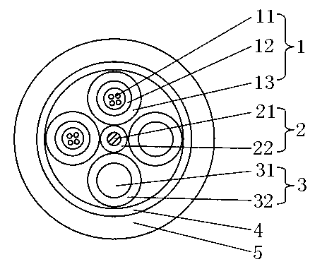
[0022] please see figure 1 , a photoelectric composite cable, which includes at least one optical unit 1, a strengthening member 2, at least two electrical units 3 and a sheath 5, the optical unit and the electrical unit are twisted around the strengthening member to form a cable core, and the sheath is located between the cable core In addition, the electrical unit is composed of a conductor 31 and an insulating layer 32 coated outside the conductor. It is characterized in that each optical unit consists of a plurality of optical fibers 11, a first protective layer 12 covering the optical fibers, and a first protective layer located on the first protective layer. The second protective layer 13 is formed outside the layer, and the diameter of the optical unit is the same as that of the electrical unit.

[0023] Of course, the above-mentioned photoelectric composite cable may also include filling ropes to replace the positions of some optical units.

Embodiment 2

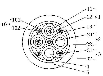
[0025] please see figure 2 , a photoelectric composite cable, which includes at least one optical unit 1, a strengthening member 2, at least two electrical units 3, a plurality of loose tubes 10 and a sheath 5, the optical unit, the loose tube and the electrical unit are twisted around the reinforcing member Combined to form a cable core, the sheath is located outside the cable core, the electrical unit is composed of a conductor 31 and an insulating layer 32 covering the conductor, and the loose tube is composed of an optical fiber 102 and a sleeve 101 covering the optical fiber. Each optical unit is composed of a plurality of optical fibers 11, a first protective layer 12 covering the optical fibers, and a second protective layer 13 outside the first protective layer; the diameter of the optical unit is the same as that of the electrical unit; The loose tube is located in the outer gap between the adjacent optical unit or the adjacent electrical unit or the adjacent optic...

Embodiment 3

[0027] please see image 3 , and refer to figure 2 , a photoelectric composite cable, basically the same as the embodiment 2, except that a loose tube is replaced by a filler 6, and the size of the filler is the same as the diameter of the loose tube.

[0028] Certainly, it is also possible that a plurality of loose tubes are replaced by fillers 6 .

[0029] The photoelectric composite cable described in any of the above-mentioned implementation examples is characterized in that the reinforcement is composed of a reinforcement member 21 or a reinforcement member 21 and a bedding layer 22 extruded on the reinforcement member.

[0030] The photoelectric composite cable described in any of the above implementation examples is characterized in that there is a moisture barrier layer 4 between the cable core and the sheath.

[0031] The photoelectric composite cable described in any of the above implementation examples is characterized in that the optical fiber or opti...


PUM


Abstract

The invention belongs to the technical field of cables, and particularly discloses a photoelectric composite cable which comprises at least one optical unit, a reinforcing part, at least two electric units and a sheath. The optical units and the electric units are stranded around the reinforcing part to form a cable core, the sheath is positioned on the outside of the cable core, and each electric unit comprises a conductor and an insulating layer covering the outside of the conductor. The photoelectric composite cable is characterized in that each optical unit comprises a plurality of light-guide fibers, a first protective layer and a second protective layer, each first protective layer covers the corresponding light-guide fibers, each second protective layer is positioned on the outside of the corresponding first protective layer, and the diameter of each optical unit is identical to that of each electric unit. The photoelectric composite cable has the main advantages that the photoelectric composite cable is small in outer diameter and occupied space, low in material consumption and convenient to construct, and is light; and the photoelectric composite cable is convenient to manufacture, and can be manufactured by existing equipment without additional investment in the aspect of equipment.

Description

technical field [0001] The invention belongs to the technical field of cables, in particular to a photoelectric composite cable. Background technique [0002] Photoelectric composite cables are being widely used. The communication industry standard of the People's Republic of China "YD / T 2159-2010 Photoelectric Hybrid Cables for Access Networks" stipulates the structure and technical parameters of some photoelectric hybrid cables. The loose tube of the optical unit, the metal wire pair for communication, the feeder wire, and the possible filling rope are twisted around the central reinforcement. If necessary, a moisture barrier is placed outside the strand, and a sheath layer is extruded outside the moisture barrier. . With the above-mentioned structure, in order to make the hybrid cable more round, easy to shape, coil, and route, etc., no matter how many optical fibers are in a single loose tube, it is generally necessary to make the outer dimensions of the loose tube t...

Claims


Application Information

Patent Timeline
Patent Type & Authority Applications(China)
IPC IPC(8): H01B11/22G02B6/44
Inventor 沈群华
Owner SHANTOU HIGH TECH ZONE AOXING OPTICAL COMM EQUIP
Why Eureka
Try Eureka