Reconstruction method for water-proof shell

A water-proof and water-layer technology, which is used in earth-moving drilling, wellbore lining, tunnel lining, etc., can solve the problems such as the inability to guarantee the safety of mine production, the inability of efficient and continuous mining of ore deposits, and the increase of the burden of mine drainage, so as to avoid surface collapse. , The effect of reducing the amount of drying and preventing the reduction of the water level

Inactive Publication Date: 2013-04-10
CENT SOUTH UNIV
View PDF7 Cites 13 Cited by
  • Summary
  • Abstract
  • Description
  • Claims
  • Application Information

AI Technical Summary

Problems solved by technology

The traditional water control scheme based on dredging and drainage, due to the dredging of a large amount of groundwater during the mining process, the groundwater level in the mining area will drop, forming a large-scale descending funnel, which will easily cause surface subsidence and form a series of geological disasters. Not only does it increase the drainage burden of the mine, which makes it impossible for the ore deposit to be mined efficiently and continuously, but also easily leads to conflicts between workers and peasants
If the water prevention and control plan of retaining the roof protection mine and constructing horizontal normal grouting holes to the water-bearing roof with a mesh size of 10m×10m is still adopted, it will not only waste a lot of mineral resources (the amount of ore mined only accounts for one-third of the remaining ore amount) one or so), and there is a threat of flooding the well
If only grouting reinforcement is carried out in the roof aquifer, and the karst water inrush from the lateral rock mass or floor rock mass is ignored, the safety of mine production cannot be guaranteed.

Method used


Image

  • Reconstruction method for water-proof shell
  • Reconstruction method for water-proof shell
  • Reconstruction method for water-proof shell

Examples


Embodiment Construction

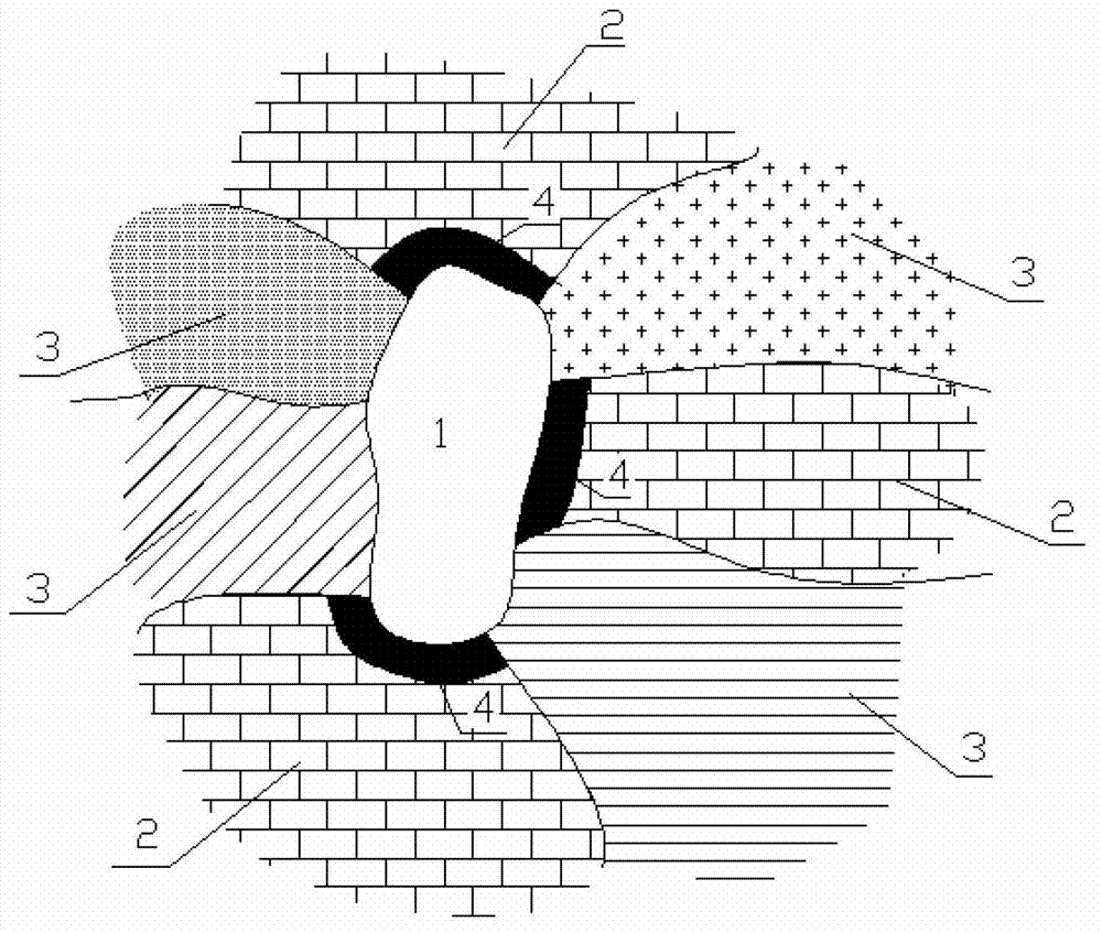
[0029] The specific use case of water-proof shell reconstruction proposed by the present invention is an example of the case where the roof rock mass is an aquifer:

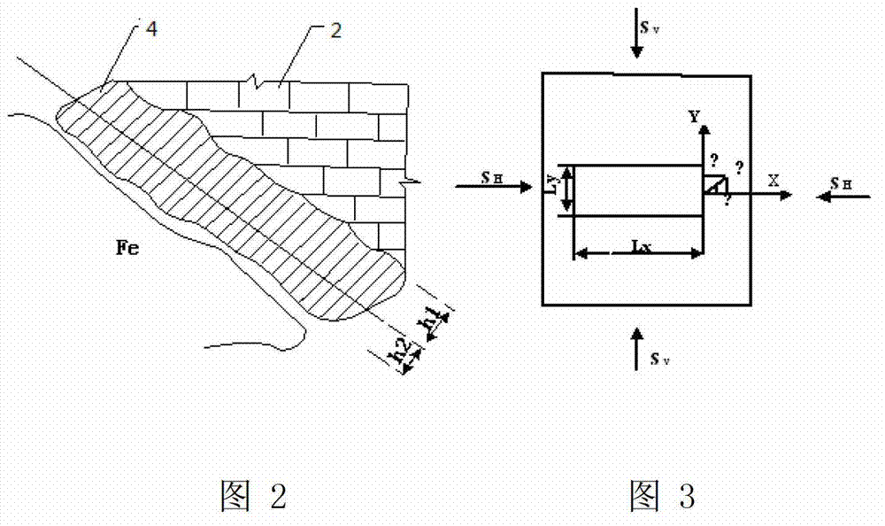
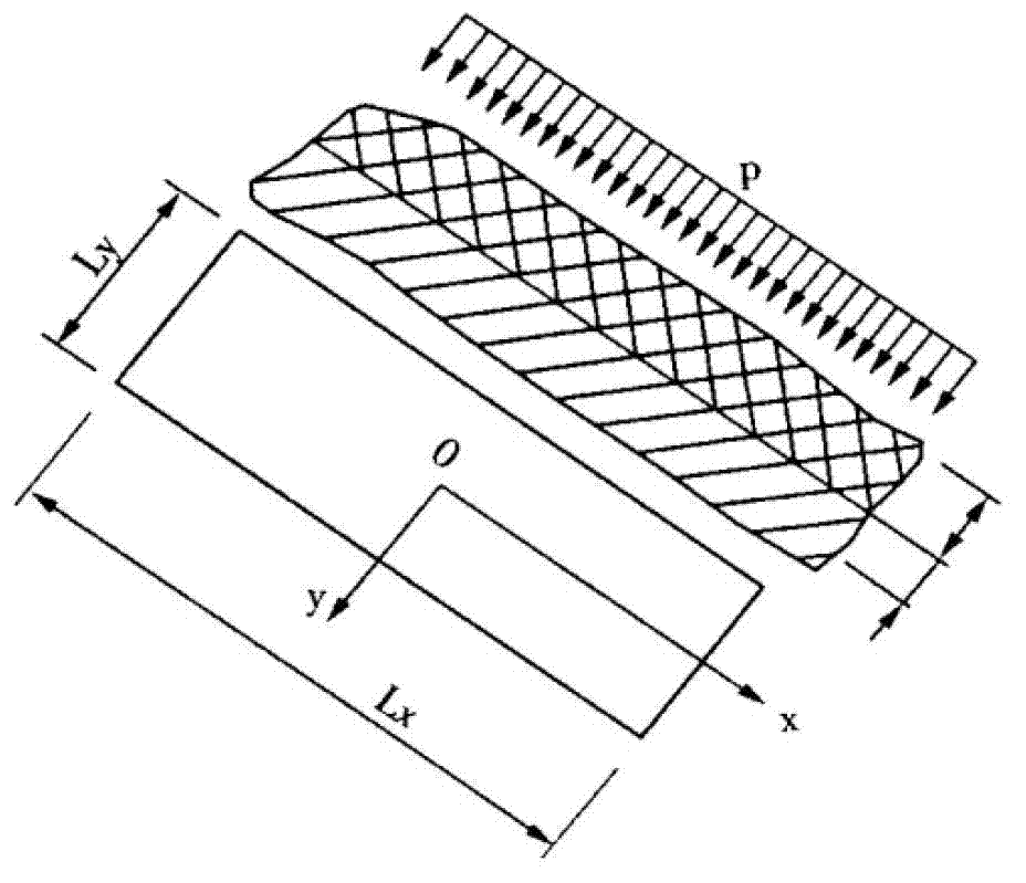
[0030] see figure 1 , figure 2 , image 3 , Figure 4 , Figure 5 , Figure 6 and Figure 7 , in the figure: 1 is the ore body; 2 is the aquifer; 3 is the aquifer rock or weakly permeable rock; 4 is the water-resisting shell; 5 is the karst cave or fissure in the aquifer; Injection chamber; 8 is a grouting hole; the water-proof shell reconstruction method provided by the invention is: collect geological data and carry out corresponding geological survey, determine the distribution of aquifers around the deposit and various stresses and hydrological parameters of surrounding rocks; The shell includes an invalid thickness h 2 and effective thickness h 1 , according to the mining design parameters to establish a mechanical model, combined with the boundary conditions, Mohr-Calomb failure criterion and fract...


PUM


Abstract

The invention discloses a reconstruction method for a water-proof shell. The distribution condition of aquifers around an ore body is determined; reconstruction of the water-proof shell is performed in the aquifers; and a complete continuous water-proof key layer is formed around the ore body. The required thickness of a water-proof top plate is calculated in combination with an actual engineering condition and a mechanical principle. Whether damage occurs is judged by simulating water-proof shell stress, plastic zone and settlement distribution condition by utilizing Flac3d under an ore body mining condition. In engineering implementation, detection holes are firstly formed in the aquifers and positions of karst caves and fissures are determined by using a geological survey instrument, connection roadways are constructed in the aquifers around a middle section, and drilling and grouting underground chambers are constructed on parts of the roadway close to the fissures of the aquifers. Grouting holes are rationally arranged in the roadways and the underground chambers and encrypted grouting is performed, and finally, inter-hole CT (Computed Tomography) fluoroscopy is performed to check the grouting and water plugging effect. According to the method, a mine floor mining environment is reconstructed, so that mine floor mining is performed safely and efficiently, and geological disasters are effectively reduced.

Description

technical field [0001] The invention relates to a method for rebuilding a water barrier in the field of mine safety. Background technique [0002] For the mining of large water karst ore bodies, it is particularly important to adopt an effective groundwater prevention and control plan. The traditional water control scheme based on dredging and drainage, due to the dredging of a large amount of groundwater during the mining process, the groundwater level in the mining area will drop, forming a large-scale descending funnel, which will easily cause surface subsidence and form a series of geological disasters. Not only does it increase the drainage burden of mines, making it impossible to mine efficiently and continuously, but it also easily leads to conflicts between workers and peasants. If the water prevention and control plan of retaining the roof protection mine and constructing horizontal normal grouting holes to the water-bearing roof with a mesh size of 10m×10m is stil...

Claims


Application Information

Patent Timeline
Patent Type & Authority Applications(China)
IPC IPC(8): E21D11/38
Inventor 邓红卫周科平胡振襄雷涛朱哲贾明吴彦林肖雄高峰杨念哥胡建华李杰林
Owner CENT SOUTH UNIV
Why Eureka
Try Eureka