Zero rigidity vibration isolator and vibration isolation system for angularly decoupling sliding oscillating bearing

A sliding joint, vibration isolator technology, applied in spring/shock absorber, vibration suppression adjustment, mechanical equipment, etc., can solve the problem of high angular stiffness and natural frequency, poor positioning accuracy of air spring vibration isolator, large pendulum length, etc. problems, to achieve the effect of small wear and additional angular stiffness, low positioning accuracy and high bearing capacity

Active Publication Date: 2013-04-10
HARBIN INST OF TECH
View PDF13 Cites 12 Cited by
  • Summary
  • Abstract
  • Description
  • Claims
  • Application Information

AI Technical Summary

Problems solved by technology

The problems of this method are as follows: 1) Due to the constraints of material properties and structural stiffness, the amplitude of vertical and horizontal stiffness reduction of the vibration isolator is limited; 2) The vertical and horizontal positioning accuracy of the air spring vibration isolator is very poor, It cannot meet the requirements of the photolithography process; 3) To achieve a lower horizontal stiffness requires a larger pendulum length, resulting in excessive height of the vibration isolator, prone to string-film resonance, and poor stability
The problems of this solution are: 1) In the disclosed technical solution, the vibration isolator cannot achieve precise positioning; 2) In the patent EP1803965A2, there is no degree of freedom of angular movement around the hori

Method used


Image

  • Zero rigidity vibration isolator and vibration isolation system for angularly decoupling sliding oscillating bearing
  • Zero rigidity vibration isolator and vibration isolation system for angularly decoupling sliding oscillating bearing
  • Zero rigidity vibration isolator and vibration isolation system for angularly decoupling sliding oscillating bearing

Examples


Embodiment Construction

[0034] Specific embodiments of the present invention are given below in conjunction with the accompanying drawings.

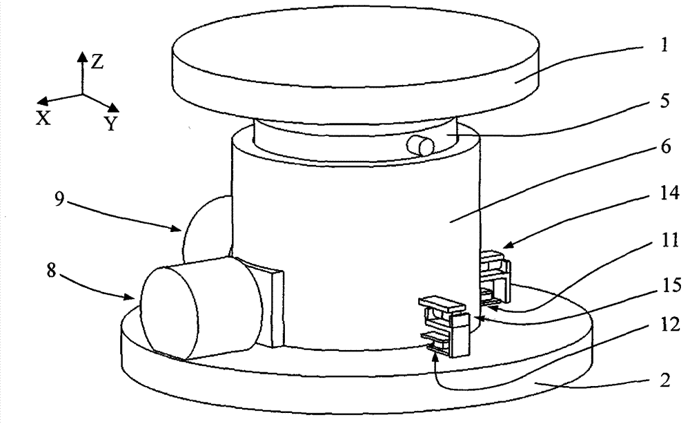
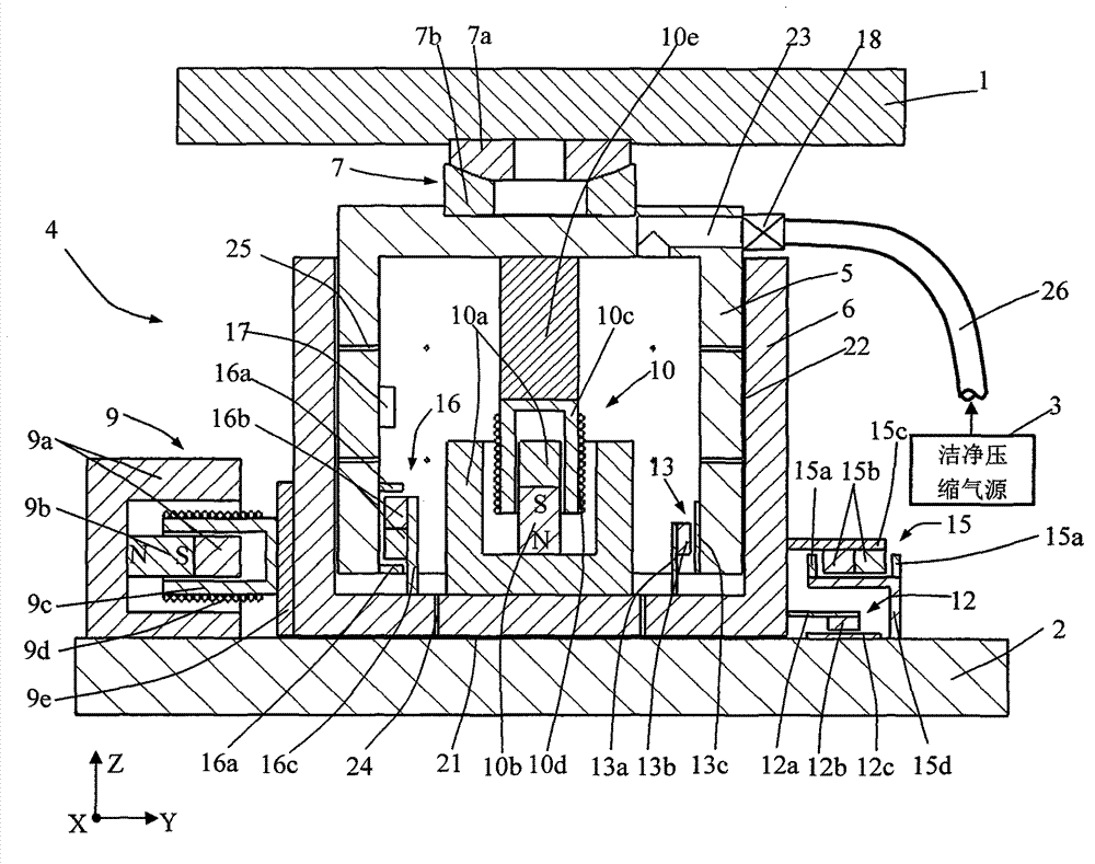
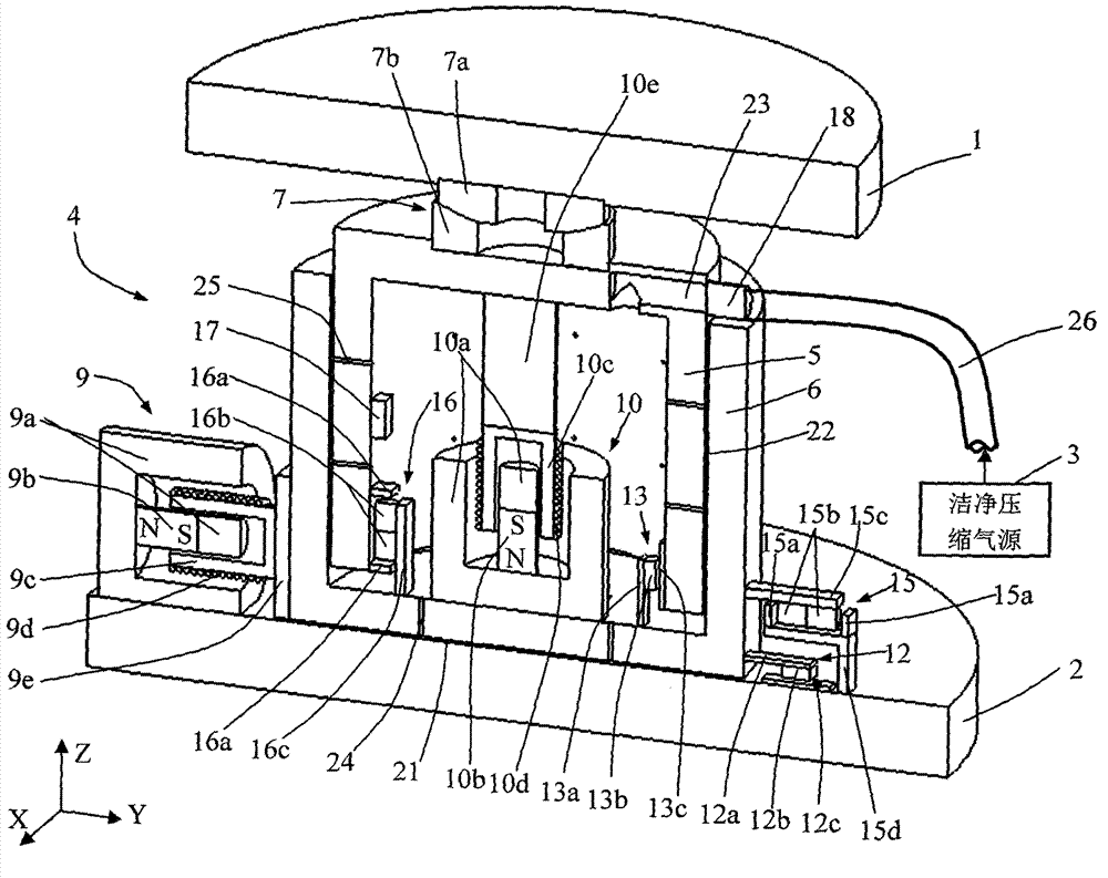
[0035] A zero-stiffness vibration isolator for angular decoupling of sliding joint bearings, consisting of an upper mounting plate 1, a lower mounting plate 2, a clean compressed air source 3, an air pipe 26 and a vibration isolator body 4, the vibration isolator body 4 is installed on the upper Between the mounting plate 1 and the lower mounting plate 2, the clean compressed air source 3 is connected to the vibration isolator main body 4 through the air pipe 26. In the structure of the vibration isolator main body 4, the lower surface of the sleeve 6 passes through the lower mounting plate 2. The axial bearing plane air bearing surface 21 is lubricated and supported, the piston barrel 5 is installed in the sleeve 6 undercut, and is lubricated and supported with the sleeve 6 through the radial bearing cylindrical air bearing surface 22, and the sliding joint bea...


PUM


Abstract

A zero rigidity vibration isolator and a vibration isolation system for angularly decoupling sliding oscillating bearing belong to the technical field of precise vibration isolation. Air floatation surfaces are respectively arranged between a sleeve of a vibration isolator main body and a lower mounting plate as well as a piston cylinder and the sleeve to lubricate and support, the angular motion freedom between an upper mounting plate and the lower mounting plate is decoupled through the sliding oscillating bearing, a voice coil motor, a displacement sensor, a limiting switch, and a controller and an actuator form a closed position loop feedback control system which is used for precisely controlling the relative positions of the upper mounting plate and the lower mounting plate. The vibration isolator has the characteristics of zero rigidity along the vertical direction and the horizontal direction, high positioning precision and angular decoupling, can obtain extremely low inherent frequency and excellent low frequency/ultralow frequency vibration isolation performance, and accordingly, the high-performance isolation vibration problem of ultra precise measurement instruments and processing equipment, in particular step-scan steppers can be solved effectively.

Description

technical field [0001] The invention belongs to the technical field of precision vibration isolation, and mainly relates to a zero-stiffness vibration isolator and vibration isolation system for angular decoupling of sliding joint bearings. Background technique [0002] With the continuous improvement of ultra-precision machining and measurement accuracy, environmental vibration has become an important factor restricting the improvement of the accuracy and performance of ultra-precision machining equipment and measuring instruments. In particular, the ultra-large-scale integrated circuit processing equipment represented by the step-scan lithography machine is extremely technically intensive and complex, and the key technical indicators have reached the limit of the existing technology, representing the highest level of ultra-precision processing equipment. Precision vibration isolation has become the core key technology in this type of equipment; the line width of the step-a...

Claims


Application Information

Patent Timeline
IPC IPC(8): F16F15/027
Inventor 崔俊宁谭久彬王雷
Owner HARBIN INST OF TECH
Why Eureka
Try Eureka