
Z scanning optical nonlinear measurement device and method capable of observing and monitoring in real time

A technology of optical nonlinearity and measuring devices, applied in the field of nonlinear optics, can solve the problems of inability to observe whether the surface topography of the sample changes, neglects, and the data is inaccurate

Active Publication Date: 2013-04-10
NANJING INST OF ADVANCED LASER TECH
View PDF4 Cites 19 Cited by
  • Summary
  • Abstract
  • Description
  • Claims
  • Application Information

AI Technical Summary

Problems solved by technology

Traditional z-scanning is only suitable for nonlinear measurement of transparent materials; at the same time, there is no observation system during the experiment to observe whether the surface topography of the sample changes, which makes it impossible to determine whether the nonlinear change curve of the material comes from the intrinsic effect caused by the laser or The laser causes changes in the structure of the material itself; at the same time, the design of a single optical path limits the study of the nonlinear characteristics of materials at different wavelengths; more importantly, it ignores the reflected light information of the sample, making the traditional transmission z-scanning method deal with translucent or opaque samples time data inaccuracy

Method used


Image

  • Z scanning optical nonlinear measurement device and method capable of observing and monitoring in real time
  • Z scanning optical nonlinear measurement device and method capable of observing and monitoring in real time
  • Z scanning optical nonlinear measurement device and method capable of observing and monitoring in real time

Examples


Embodiment Construction

[0040] The present invention will be further described below in conjunction with embodiment and accompanying drawing, but should not limit protection scope of the present invention with this

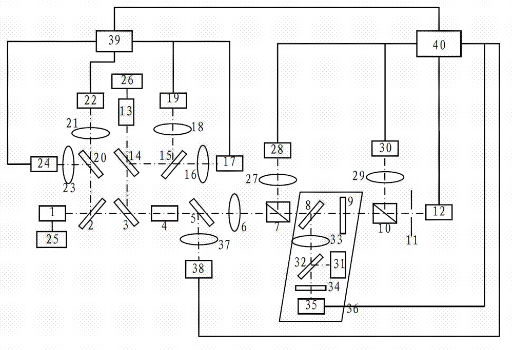
[0041] see first figure 1 , figure 1 It is an optical path structure diagram of an embodiment of the present invention that can observe and monitor the z-scan optical nonlinear measurement device in real time. It can be seen from the figure that the present invention can observe and monitor the z-scan optical nonlinear measurement device in real time, and the composition includes the output laser wavelength λ 1 The first laser 1 and the output laser wavelength λ 2 The second laser 13, the main optical axis formed along the main optical path of the laser output of the first laser 1 is the first beam splitter 2, the first laser beam splitter 3, the beam expander 4, the second beam splitter 5 , the first objective lens 6, the first beam splitter 7, the second laser beam splitter 8, the sa...


PUM

PropertyMeasurementUnit
reflectanceaaaaaaaaaa
transmittivityaaaaaaaaaa

Abstract

The invention relates to a z scanning optical nonlinear measurement device and method capable of observing and monitoring in real time. The device mainly comprises a light source modulating and monitoring part, a data collecting part and a luminance observing part. The device adopts two light sources, so that the light sources can be switched conveniently, the pulse width and the pulse period of an emitted laser can be controlled through a signal generator, and the power is adjustable; the data of a transmission open hole and a transmission closed hole of a measured sample can be measured; and the data of a reflection open hole can be measured. According to the invention, the device and the method are suitable for not only the measurement of the nonlinear absorption coefficient and the nonlinear refractive index of a transparent material, but also the nonlinear measurement of an opaque material. A micro-objective, a lighting source and a CCD (Charge Coupled Device) camera are added for a sample moving platform in the device, so that the surface feature of the sample can be observed in real time, and the impact on the measurement data caused by the change of the feather of the sample can be avoided. While an oscilloscope is added to monitor the wave form and the power of the acting laser in real time, and the precision and the accuracy of the nonlinear measurement of material are improved.

Description

technical field [0001] The invention relates to nonlinear optics, in particular to a z-scan optical nonlinear measurement device and method capable of real-time observation and monitoring. Background technique [0002] In recent years, the application of all-optical switches and optical sensors has made researchers more interested in materials with larger and faster nonlinear properties. The research mainly includes nonlinear refractive index and nonlinear absorption coefficient of materials. With the rapid development of nonlinear optical materials, more sensitive nonlinear measurement methods are needed. At present, the main nonlinear coefficient measurement methods include degenerate four-wave mixing method, dual-wave coupling method, ellipsometry, beam distortion method and Optical Kerr effect method, etc. These measurement methods have complex measurement equipment, high cost, unsatisfactory accuracy and efficiency, and cannot achieve ideal measurement results. [0003...

Claims


Application Information

Patent Timeline
Patent Type & Authority Applications(China)
IPC IPC(8): G01N21/41G01N21/17
Inventor 王睿魏劲松
Owner NANJING INST OF ADVANCED LASER TECH
Learn More