Control device and control method of synchronous motor

A technology for synchronous motors and control devices, which is applied in the direction of motor generator control, AC motor control, and electromechanical transmission control. The effect of stable switching

Active Publication Date: 2013-04-10
SANKEN ELECTRIC CO LTD
View PDF6 Cites 12 Cited by
  • Summary
  • Abstract
  • Description
  • Claims
  • Application Information

AI Technical Summary

Problems solved by technology

[0005] However, in Patent Document 1, the input specification of the main circuit part is a specific motor whose input specification is a battery-based DC power supply. The problem that I cannot cope with any motor
That is, in Patent Document 1, a relatively stable battery is used as a DC power supply, but

Method used


Image

  • Control device and control method of synchronous motor
  • Control device and control method of synchronous motor
  • Control device and control method of synchronous motor

Examples


Embodiment Construction

[0047] Next, embodiments of the present invention will be specifically described with reference to the drawings.

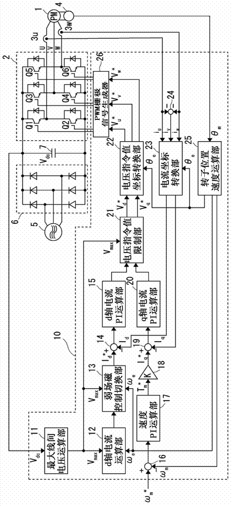
[0048] This embodiment is a control device for driving and controlling a permanent magnet synchronous motor (hereinafter referred to as PM motor 1 ) as a synchronous motor. Refer to figure 1, has an inverter circuit 2 , a U-phase current sensor 3 u , a W-phase current sensor 3 w , an encoder 4 , and a control unit 10 . The power supply is a DC power supply based on 3-phase AC + diode rectification. The three-phase AC power supply 5 is rectified by the diode bridge circuit 6, and the DC voltage Vdc whose ripples have been removed by the smoothing capacitor 7 is supplied to the inverter circuit 2. The converter circuit 2 outputs variable voltage, variable frequency three-phase AC and applies it to the PM motor 1.

[0049] The inverter circuit 2 is composed of bridge-connected switching elements Q1 to Q6. As the switching elements Q1 to Q6 , NPN bipolar transistors...


PUM


Abstract

The invention provides a control device and a control method of a synchronous motor. The device comprises a d-axis current calculation portion (12) which calculates d-axis current calculation value for controlling weak field magnet based on a maximum line-to-line voltage (Vmax) calculated by a maximum line-to-line voltage calculation portion and an electric angle speed (Omega e) of a PM motor (1), and a weak field magnet control switching portion (13) which outputs any one of the d-axis current calculation value for controlling weak field magnet and a d-axis current setting value for controlling maximum torque as a d-axis current instruction value (Id*)according to the maximum line-to-line voltage (Vmax) and the electric angle speed (Omega e) of a PM motor (1). The d-axis current calculation value is calculated by the d-axis current calculation portion (12) based on the maximum line-to-line voltage (Vmax) and the electric angle speed (Omega e) of the PM motor (1) as counter electromotive force factors (Ke) of the motor parameters of the PM motor (1).

Description

technical field [0001] The present invention relates to a control device and a control method of a synchronous motor, in particular to a control device and a control method of a synchronous motor which can stably switch to weak-field magnetic control. Background technique [0002] When the permanent magnet synchronous motor is controlled at a speed equal to or higher than the base rotational speed, switching is performed for field-weakening control in which the magnetic flux generated by the permanent magnets is controlled to be weak by the d-axis current. Judgment on the switching of field-weakening control is based on the comparison between the base speed and the motor speed. However, in the case of devices with large DC voltage fluctuations, sometimes the inverter output voltage is saturated at speeds below the base speed and cannot be adjusted. Take control. [0003] Therefore, the applicant of the present invention disclosed a technology capable of stably switching bet...

Claims


Application Information

Patent Timeline
IPC IPC(8): H02P21/06H02P27/06H02P21/00H02P6/06H02P6/08H02P6/17H02P6/28H02P21/05H02P21/22H02P23/04H02P23/16H02P27/04H02P27/08
Inventor 中岛洋一郎
Owner SANKEN ELECTRIC CO LTD
Why Eureka
Try Eureka