

Electrically heated catalyst
An electric heating and catalyst technology, which is applied in the direction of catalyst activation/preparation, physical/chemical process catalysts, chemical instruments and methods, etc., can solve the problem of insulation resistance drop and achieve the effect of suppressing the drop of insulation resistance
- Summary
- Abstract
- Description
- Claims
- Application Information
AI Technical Summary
Problems solved by technology
Method used
Image

Examples
Embodiment 1
[0038] (Brief structure of EHC)
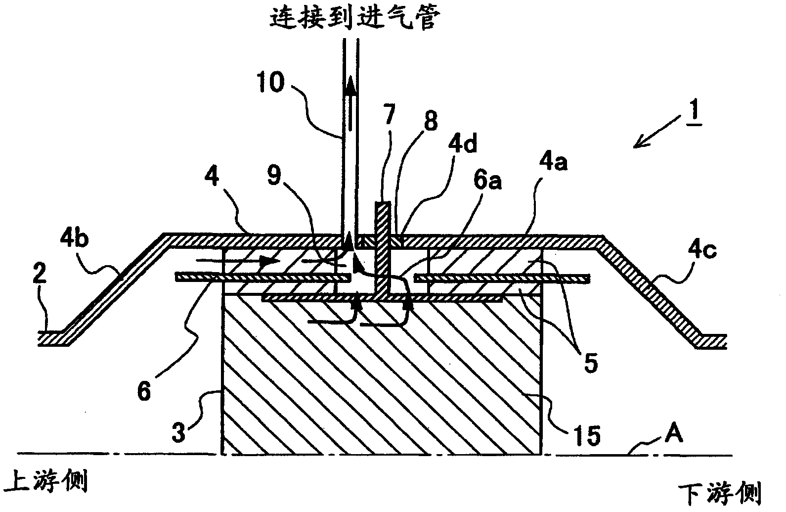
[0039] figure 1 It is a figure which shows the schematic structure of the electrically heated catalyst (EHC) which concerns on this Example. The EHC 1 according to this embodiment is installed on an exhaust pipe of an internal combustion engine mounted on a vehicle. The internal combustion engine can be a diesel engine or a gasoline engine. Furthermore, the EHC 1 according to the present embodiment can also be applied to a vehicle employing a hybrid system including an electric motor.
[0040] figure 1 It is a cross-sectional view of the EHC 1 cut longitudinally along the central axis A of the exhaust pipe 2 of the internal combustion engine. In addition, since the shape of EHC1 is line-symmetric with respect to the central axis A, for convenience, in figure 1 Only the upper part of EHC1 is shown in .
[0041] The EHC 1 according to this embodiment includes a catalyst carrier 3 , a container 4 , a gasket 5 , an inner tube 6 , an electrod...
Embodiment 2
[0058] (Brief structure of EHC)
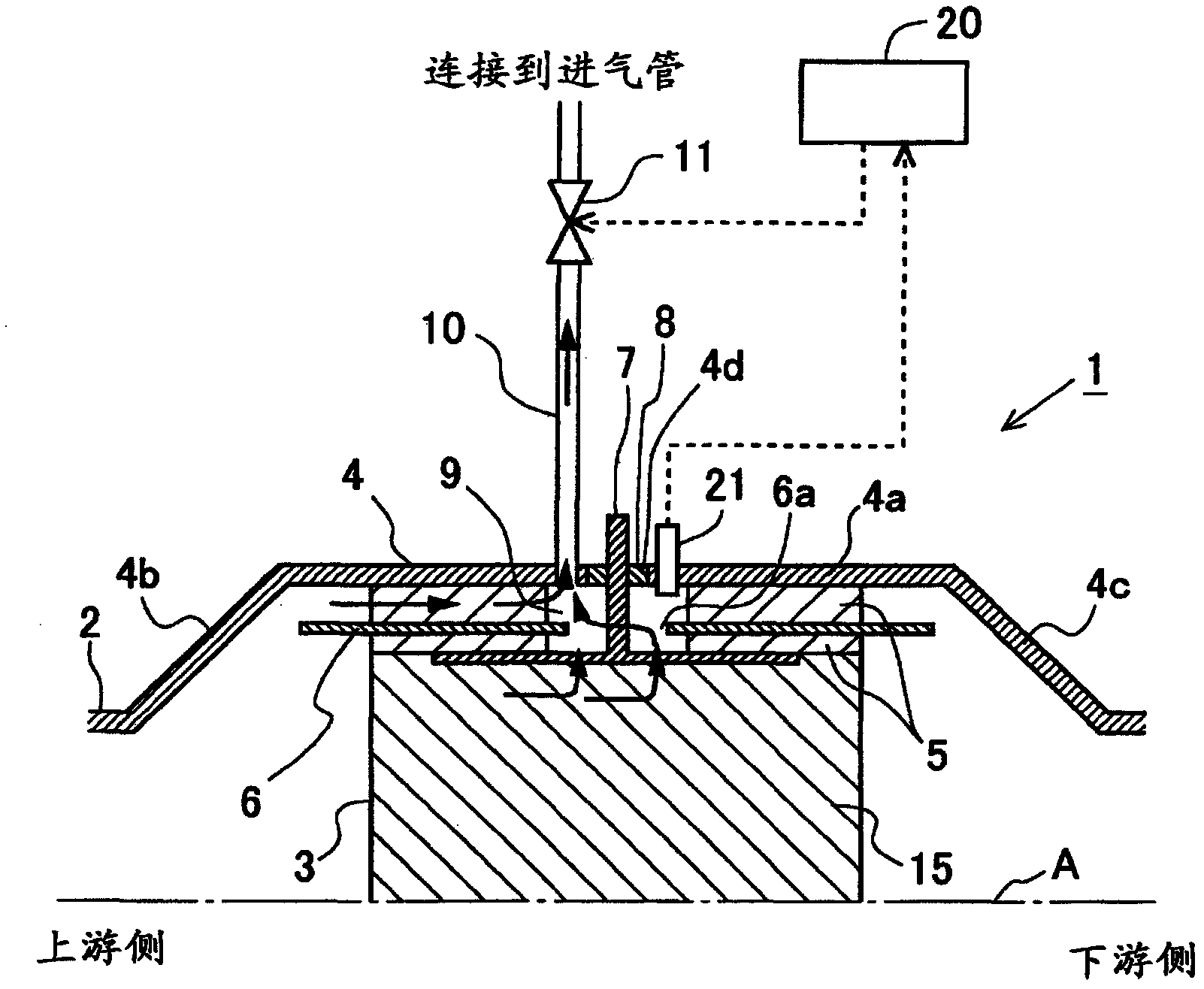
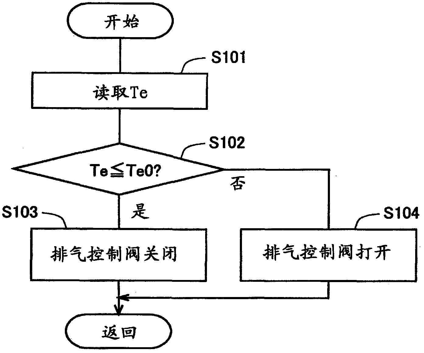
[0059] figure 2 It is a figure which shows the schematic structure of the EHC concerning this Example. In this embodiment, a temperature sensor 21 for detecting the temperature in the electrode chamber 9 is provided on the EHC 1 . The detected value of the temperature sensor 21 is input to an electronic control unit (ECU) 20 . Furthermore, a ventilation control valve 11 is provided on the ventilation passage 10 . The ventilation control valve 11 is controlled by the ECU 20 . If the ventilation control valve 11 is opened, the ventilation passage 10 is opened; if the ventilation control valve 11 is closed, the ventilation passage 10 is disconnected. The structure other than that is the same as that of the EHC related to Example 1. In addition, in this embodiment, the temperature sensor 21 corresponds to the temperature acquisition part concerning this invention. However, the ECU 20 can also calculate the amount of heat supplied to the ele...
Embodiment 3
[0069] (Brief structure of EHC)
[0070] Figure 4 It is a figure which shows the schematic structure of the EHC concerning this Example. In this embodiment, as shown in Embodiment 1, the ventilation passage is directly connected to the electrode chamber 9 . In this embodiment, the ventilation passage 12 is connected to a portion where the gasket 5 is located on the upstream side of the electrode chamber 9 . The structure other than that is the same as that of the EHC related to Example 1.
[0071] (Effect of the structure of the EHC related to this embodiment)
[0072] Figure 4 In , the arrows also indicate the flow of exhaust gas, condensed water, and water vapor generated by the evaporation of condensed water. According to the present embodiment, by ventilating through the ventilation passage 12 , water vapor and exhaust gas entering the gasket 5 along the flow of the exhaust gas from the upstream side are introduced into the ventilation passage 12 before reaching the...
PUM
 Abstract
Description
Claims
Application Information