Heat dissipation frame manufacturing method and products thereof

A heat dissipation frame and manufacturing method technology, applied in the field of heat dissipation frame manufacturing and its products, can solve the problems of high production cost, limited heat conduction efficiency of heat dissipation structure, etc., achieve the effects of reducing the consumption of man-hours, saving processing steps, and reducing manufacturing costs

Inactive Publication Date: 2013-04-17
GOANG HANN ENTERPRISE
View PDF4 Cites 9 Cited by
  • Summary
  • Abstract
  • Description
  • Claims
  • Application Information

AI Technical Summary

Problems solved by technology

[0006] The object of the present invention is to provide a method for manufacturing a heat dissipation frame and its products, which are used to overcome the shortcomings of the existing backlight module heat dissipation structure, such as limited heat conduction efficiency and high production costs.

Method used


Image

  • Heat dissipation frame manufacturing method and products thereof
  • Heat dissipation frame manufacturing method and products thereof
  • Heat dissipation frame manufacturing method and products thereof

Examples


Embodiment Construction

[0025] Relevant detailed description and technical content of the present invention, now just explain as follows with respect to matching drawing:

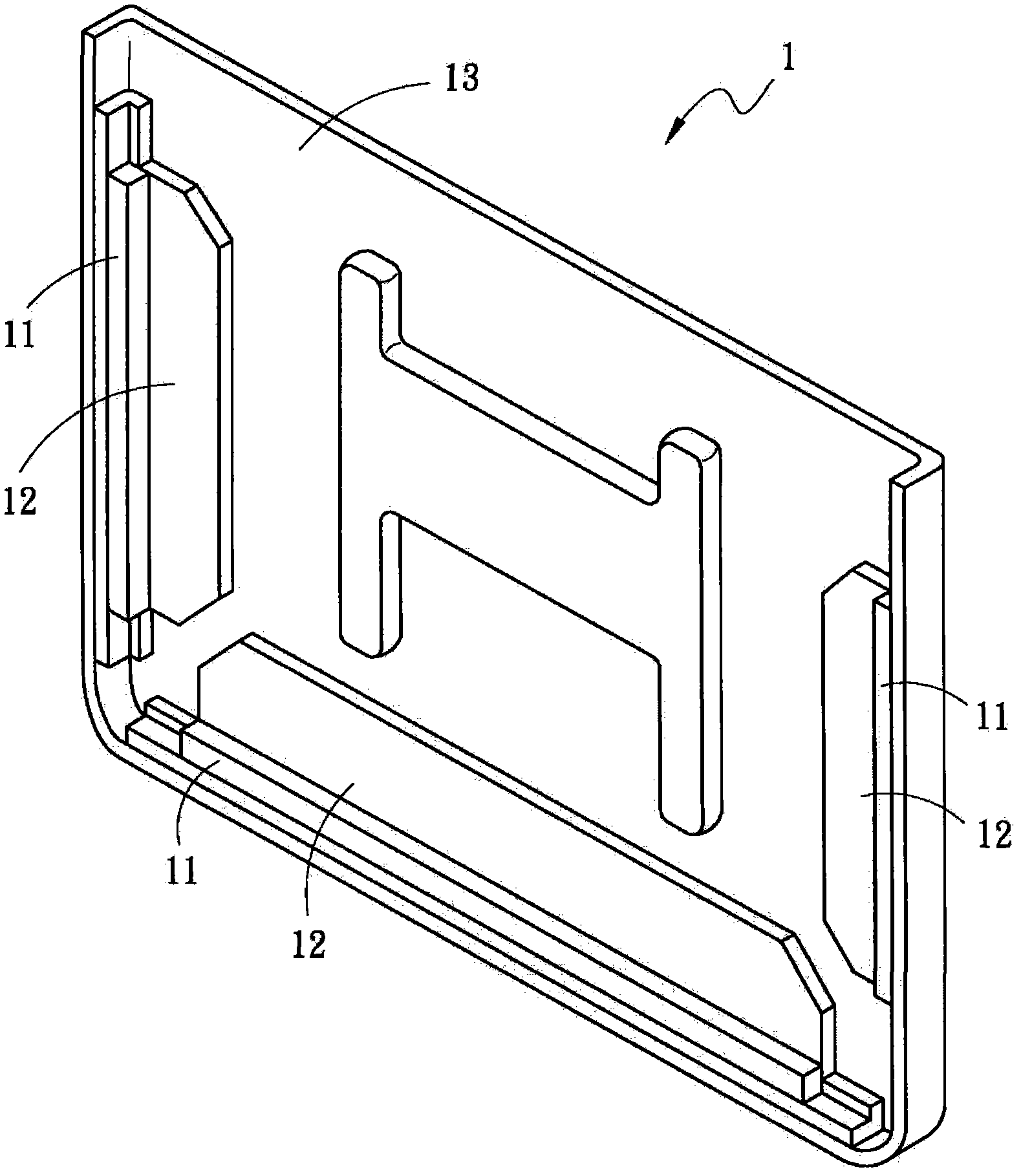
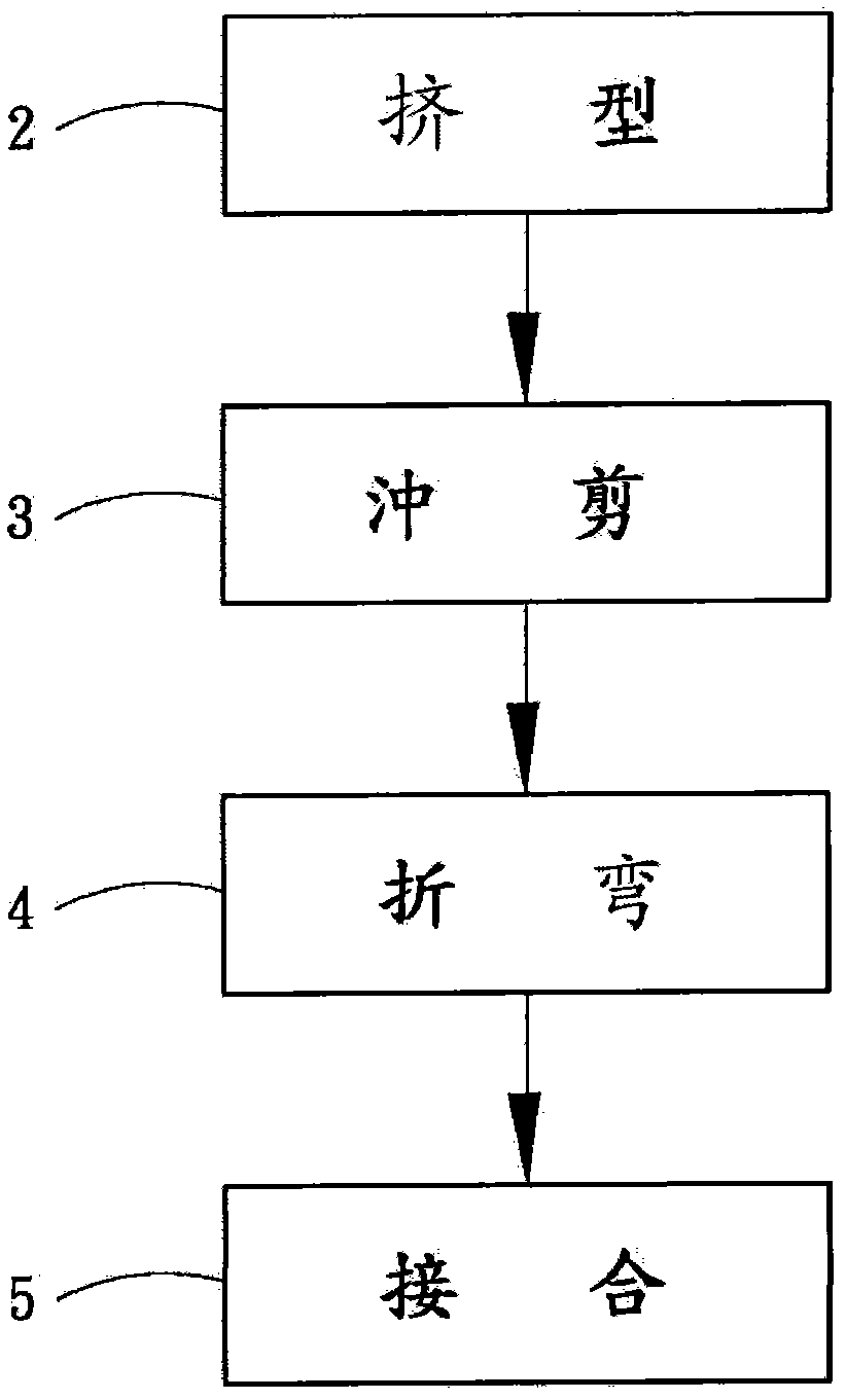
[0026] see figure 2 As shown, the present invention provides a method for manufacturing a heat dissipation frame, which includes the following steps:

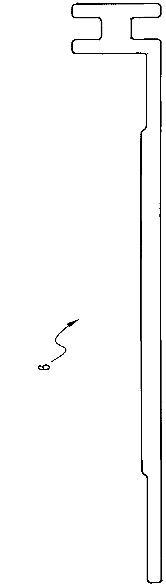
[0027] a. Extrusion Step 2: Extrude the aluminum material into the initial shape of the heat sink.

[0028] b. Punching and shearing step 3: After measuring according to the required size specifications, perform partial punching and shearing at the place where the long side of the heat sink prototype is to be bent to form multiple punching and shearing gaps.

[0029] c. Bending step 4: Bending the initial form of the heat sink at the punching and shearing gap and butting with each other to form multiple bending angles.

[0030] d. Joining step 5: Joining and fixing the butt joints of the punching and shearing notches and the joints of the head and tail joints of the bent heat si...


PUM


Abstract

The invention relates to a heat dissipation frame manufacturing method and products thereof. The heat dissipation frame manufacturing method comprises the following steps: firstly extruding an aluminum product into a cooling fin prototype; after measuring the cooling fin prototype according to needed dimensions, carrying out a local punching shear on a position to bend of the cooling fin prototype to form a plurality of punching shear gaps; bending the cooling fin prototype at the position of the punching shear gaps and forming a plurality of bending angles in a mutual butt joint mode; and fixedly jointing the butt joint positions of the punching shear gaps and the head and tail butt joint positions of the bended cooling fin to form a frame. Therefore, an extruding type cooling fin formed through a punching shear and bending can effectively reduce the procedures and save materials and reduce the cost of work hours and reach the aims of improving the heat conduction performance and lowering the manufacturing cost.

Description

technical field [0001] The invention relates to a heat dissipation frame manufacturing method and its products, in particular to a heat dissipation structure applied to a liquid crystal display backlight module. Background technique [0002] Liquid crystal displays have many advantages such as thinness, light weight, low radiation and low power consumption, which make them completely replace traditional image tube displays in just a few years and become mainstream products in the information market. However, due to the liquid crystal display panel (LCD panel) itself does not have the function of emitting light, so it is necessary to configure a backlight module behind the liquid crystal display panel to provide the light source required by the liquid crystal display panel. [0003] The traditional backlight module uses a cold cathode lamp (CCFL), which has the disadvantage of containing mercury, and has no advantages compared with light-emitting diodes (LEDs) in terms of res...

Claims


Application Information

Patent Timeline
Patent Type & Authority Applications(China)
IPC IPC(8): B23P15/26G02F1/13357
Inventor 杨建和魏才渊
Owner GOANG HANN ENTERPRISE
Why Eureka
Try Eureka