
Pipe excitation source identification and prediction method of vibration response to pipe excitation source

A technology of vibration response and prediction method, which is applied in the field of vibration reduction and noise reduction, can solve problems such as complex identification procedures, and achieve the effects of high prediction accuracy, simple prediction device, and strong applicability

Active Publication Date: 2013-04-17
HARBIN ENG UNIV
View PDF5 Cites 23 Cited by
  • Summary
  • Abstract
  • Description
  • Claims
  • Application Information

AI Technical Summary

Problems solved by technology

[0007] The above research results are all based on experiments to identify incentive sources, and the identification procedures are complicated.

Method used


Image

  • Pipe excitation source identification and prediction method of vibration response to pipe excitation source
  • Pipe excitation source identification and prediction method of vibration response to pipe excitation source
  • Pipe excitation source identification and prediction method of vibration response to pipe excitation source

Examples


Embodiment Construction

[0033] The present invention is described in more detail below in conjunction with accompanying drawing example:

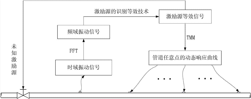
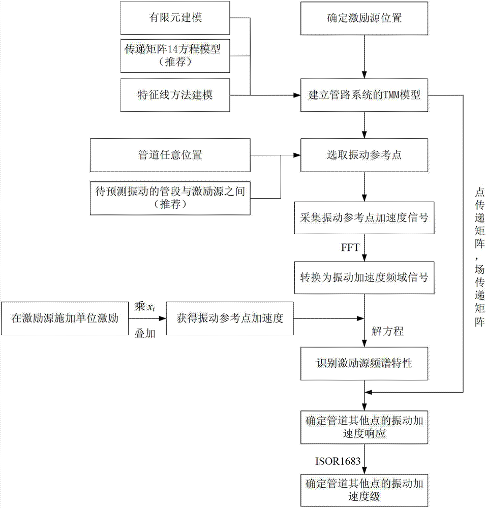
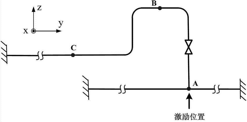
[0034] combine Figure 1~3 , the excitation source identification and vibration prediction method of the present invention comprises the following steps:

[0035] (1) Determine the position of the equivalent excitation source of the pipeline, and establish the frequency domain transfer matrix (TMM) model of the pipeline system (D tot ).

[0036] First, according to the arrangement of excitation sources such as valves, branch pipes and elbows in the pipeline system, determine the location and number n of excitation sources, and assume that the size of the i-th excitation source is equal to x i (i=1,2,...n). Then according to the motion equation of the piping system, the TMM model of the piping system is established.

[0037] as attached figure 2 As shown, in addition to the TMM model of the pipeline system, the finite element (FEM) model and the characteristi...


PUM


Abstract

The invention aims at providing pipe excitation source identification and a prediction method of vibration response to a pipe excitation source. The steps are collecting a pipe wall acceleration signal and transforming the collected time domain signal into a frequency domain signal through Fourier transform, performing excitation source identification and equivalence and using a linear system superposition method to determine the size of the pipe system equivalent excitation source through comparing the experimental data with the pipe system dynamics calculation result, and using a transfer matrix method for predicting the dynamic response to the vibration of any optional position of the pipe according to the equivalent excitation. According to the pipe excitation source identification and the prediction method of vibration response to a pipe excitation source, an appropriate measuring point easy to measure is chosen according to the specific arrangement of the pipe for the excitation source size identification and the pipe vibration prediction, so that problem of the pipe system excitation source characteristics and the difficult vibration measurement of some portions of the pipe and others can be solved, the experimental measurement points arrangement can be reduced and the flexibility of the pipe vibration measurement can be increased.

Description

technical field [0001] The invention relates to a prediction method in the field of vibration reduction and noise reduction. Background technique [0002] Piping systems widely exist in petrochemical, ship operation and other industries. Vibration and noise during the working process of pipelines often have adverse effects on the working environment and the normal operation of pipeline precision instrument accessories. Therefore, the characteristics of pipeline excitation sources and their vibration Measurement and prediction become a vital part of pipeline vibration and noise control. [0003] The excitation source of the pipeline system includes not only the working parts such as valves and pumps, but also the pulsating pressure field acting on the pipe wall. Therefore, it is very complicated and difficult to accurately identify the excitation source of the pipeline. At present, there are mainly two ways to obtain the size of the pipeline excitation source, one is to inst...

Claims


Application Information

Patent Timeline
IPC IPC(8): G06F19/00G01H17/00
Inventor 李帅军柳贡民吴晓笛张文平李艳华曹贻鹏明平剑张新玉
Owner HARBIN ENG UNIV
Learn More