Hydraulic drive device for hydraulic work machine
A driving device and operating machine technology, applied in the direction of fluid pressure actuating device, transmission device control, mechanical equipment, etc., can solve the problems of difficult and complicated structure and achieve the effect of widening the range
- Summary
- Abstract
- Description
- Claims
- Application Information
AI Technical Summary
Problems solved by technology
Method used
Image

Examples
no. 1 approach
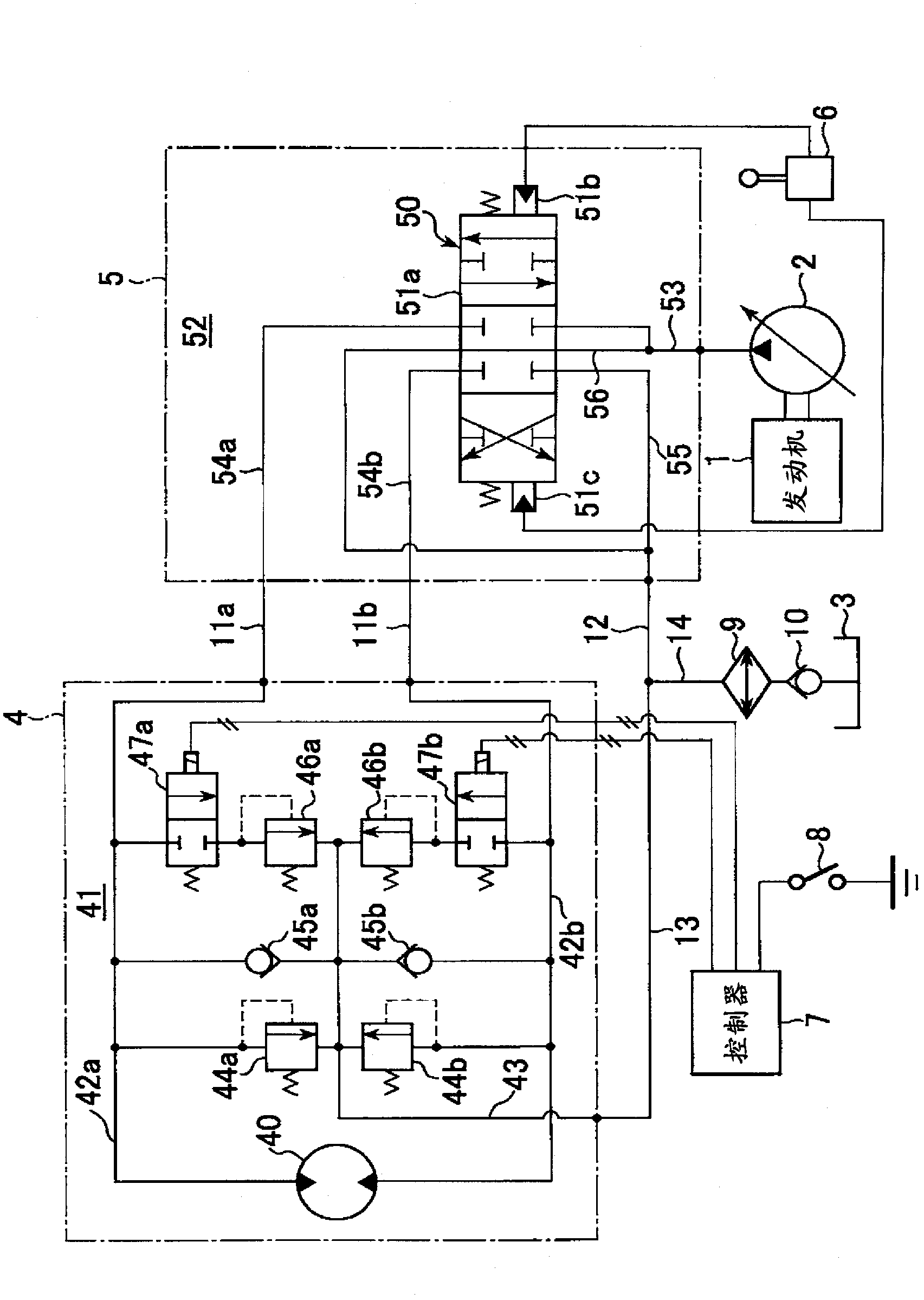
[0044] figure 1 It is a figure which shows the hydraulic drive apparatus of the hydraulic working machine which concerns on the 1st Embodiment of this invention.
[0045] The hydraulic drive device includes: a diesel engine 1 as a prime mover; a variable-capacity hydraulic pump 2 driven by the engine 1; a hydraulic oil tank 3; (Refer to figure 2 ) swivel motor unit 4 of hydraulic swivel motor 40 driven by rotation; control valve 5 with a plurality of built-in directional control valves including rotational direction control valve 50 for controlling the pressure supplied from hydraulic pump 2 to hydraulic swivel motor 40 The flow of oil is controlled; the lever device 6 for instructing the operation of the rotating body 101 ; the controller 7 ; the relief pressure change instruction switch 8 ; the oil cooler 9 ;
[0046] The control valve 5 has a valve housing 52 in which the main spool valve 51a of the rotational direction control valve 50 is arranged. Pressure receiving por...
no. 2 approach
[0089] Figure 4 It is a figure which shows the hydraulic drive apparatus of the hydraulic working machine which concerns on 2nd Embodiment of this invention. In the figure, with figure 1 Parts that are identical to those shown are given the same reference numerals.
[0090] Figure 4Among them, the rotary motor unit 4A is composed of a rotary motor section 4-1 and an additional relief valve section 4-2.
[0091] In the swing motor section 4-1, a hydraulic swing motor 40 is arranged in a casing 41-1, and a pair of actuator oil passages 42a-1 and 42b-1 and an internal discharge oil passage 43-1 are formed. In addition, a pair of first rotary relief valves 44a and 44b with no shock function and a pair of check valves 45a and 45b for replenishment are arranged.
[0092] In addition, the housing 41-1 has a first port surface 63 to which the ports 61a and 61b of the pair of actuator oil passages 42a-1 and 42b-1 and the port 62 on one end side of the internal discharge oil passa...
no. 3 approach
[0099] Figure 5 It is a figure which shows the hydraulic drive apparatus of the hydraulic working machine which concerns on 3rd Embodiment of this invention. In the figure, for the figure 1 and Figure 4 Parts that are identical to those shown are given the same reference numerals.
[0100] Figure 5 Among them, the rotary motor unit 4B is constituted by the rotary motor section 4-1B and the additional relief valve section 4-2B, and the additional relief valve section 4-2B is used as the connection between the housing 41-2 and the rotary motor section 4-1. The casing 41-1 is constituted by an independent relief valve block, the casing 41-2 is fixed to the first port surface 63 of the casing 41-1 of the rotary motor section 4-1B by bolts, etc. and assembled, thereby being combined with the rotary motor The section 4-1B is integrated, as in the second embodiment.
[0101] In this embodiment, the port of the internal discharge oil passage 43-1B is not open to the first port...
PUM
 Abstract
Description
Claims
Application Information
 - R&D Engineer
- R&D Manager
- IP Professional
- Industry Leading Data Capabilities
- Powerful AI technology
- Patent DNA Extraction
Browse by: Latest US Patents, China's latest patents, Technical Efficacy Thesaurus, Application Domain, Technology Topic.
© 2024 PatSnap. All rights reserved.Legal|Privacy policy|Modern Slavery Act Transparency Statement|Sitemap