Multi-phase, multi-frequency controller

a multi-frequency controller and multi-phase technology, applied in the direction of multiple dynamo-motor starters, motor/generator/converter stoppers, dynamo-electric converter control, etc., can solve the problem that the output frequency of current synchronous motors is limited by the load on these signal processors, and the frequency control range is expanded. problem, to achieve the effect of easy to achiev

Active Publication Date: 2009-06-18
THE BOEING CO
View PDF11 Cites 9 Cited by
  • Summary
  • Abstract
  • Description
  • Claims
  • Application Information

AI Technical Summary

Benefits of technology

[0005]The present invention is directed to a multi-phase, multi-frequency arrangement for controlling an electric motor which utilizes heterodyne conversion of control signals in combination with a voltage controlled oscillator feedback arrangement. A multi-phase ring oscillator generates plural signals having fixed phase relationships at high frequency. These phase-shifted signals are heterodyned down to a baseband frequency signal representing motor speed by means of the output of a voltage controlled oscillator to maintain frequency control as in FM radio tuning and a constant phase relationship among the reference signals. The control reference signals can be varied from DC to 100 kHz using a 0-25 MHz voltage controlled oscillator. Control of the desired baseband frequency is determined by selecting the variable oscillating frequency corresponding to the desired motor speed relative to the 3-phase ring oscillator input. Feedback and closed loop control is provided by frequency and phase discriminators using phase lock loop techniques. The selected frequency of the voltage controlled oscillator is compared with the frequency of the feedback signal for generating an error, or correction, signal frequency which is mixed with fixed phase signals output by the multi-phase ring oscillator to provide the baseband frequency signals representing motor speed correction. This approach provides precise control of the feedback signal and expands the frequency control range far beyond normal analog methods because of the natural noise immunity of the RF-based heterodyne technique. The “lock range” is expanded to very low speeds where sensor-less and analog resolver techniques may fail. The control reference signal is provided to a pulse width modulator, the pulsed output of which is provided to a standard multi-phase motor drive amplifier for providing an AC control signal to the motor as well as to the voltage controlled oscillator feedback arrangement. The inventive approach removes pulse width modulation, high speed feedback sensing, and error calculation requirements from a system microprocessor and related interface electronics. This removes various control requirements from the microprocessor which is required only to provide user interface requirements and low speed control and monitoring. By removal of the frequency generation requirements of a motor controller from the microprocessor, less hardware and software are required to control the electric motor. As faster pulse width modulators become available, the baseband frequencies will increase without the requirement to change controllers, since a frequency differential of greater than 100 kHz is easily achievable.

Problems solved by technology

In addition, a synchronous motor is not by itself inherently capable of providing variable speed operation, with its speed determined by the frequency of the input power, the nature of the load and the current available.
A large load on these signal processors limits the output frequency of current synchronous motors to on the order of 3 kHz.
Employing multiple processors to provide drive signal inputs of increased frequency substantially increases the complexity, particularly of the control software, and the expense of the synchronous motor drive arrangement.

Method used


Image

  • Multi-phase, multi-frequency controller
  • Multi-phase, multi-frequency controller

Examples


Embodiment Construction

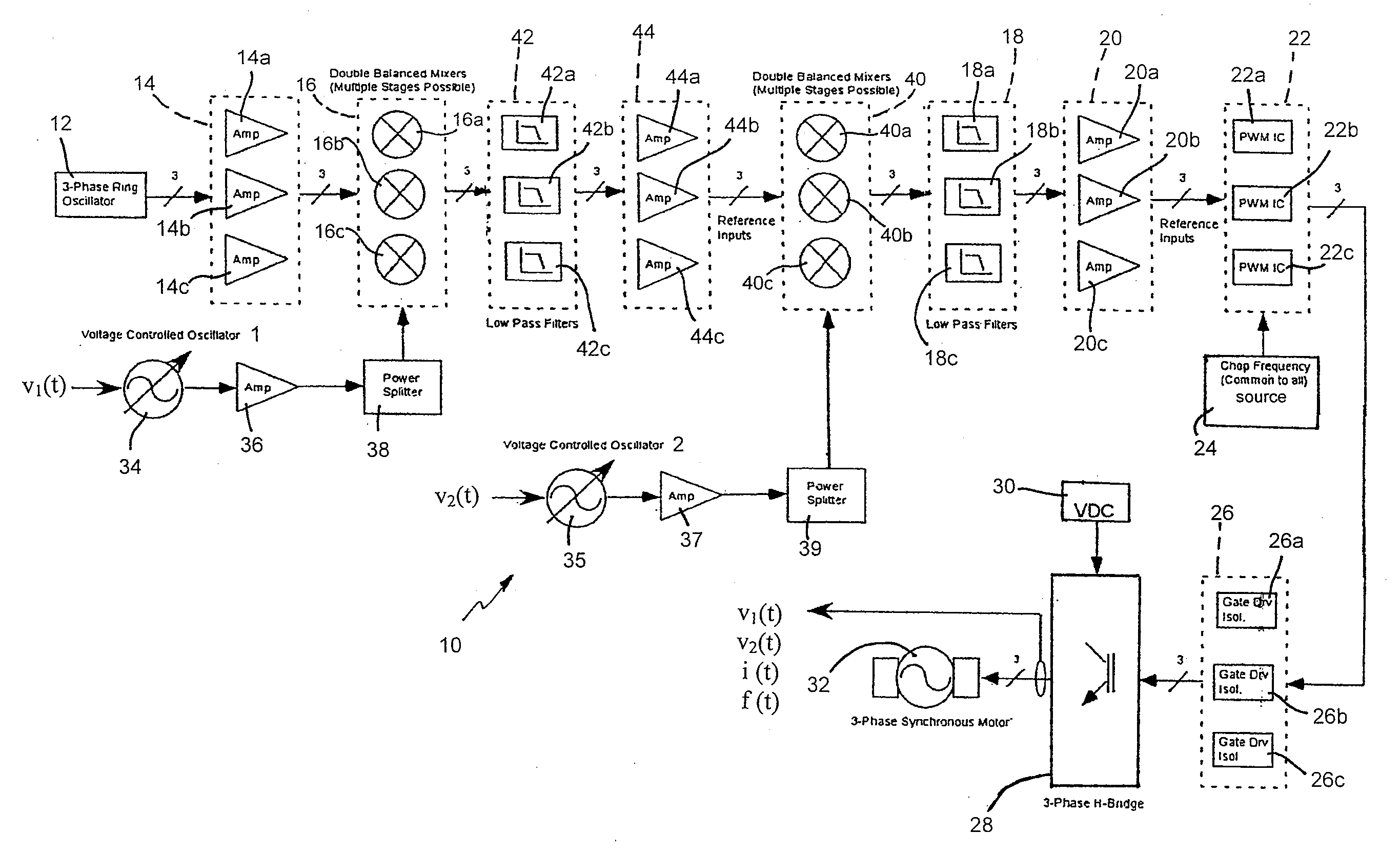
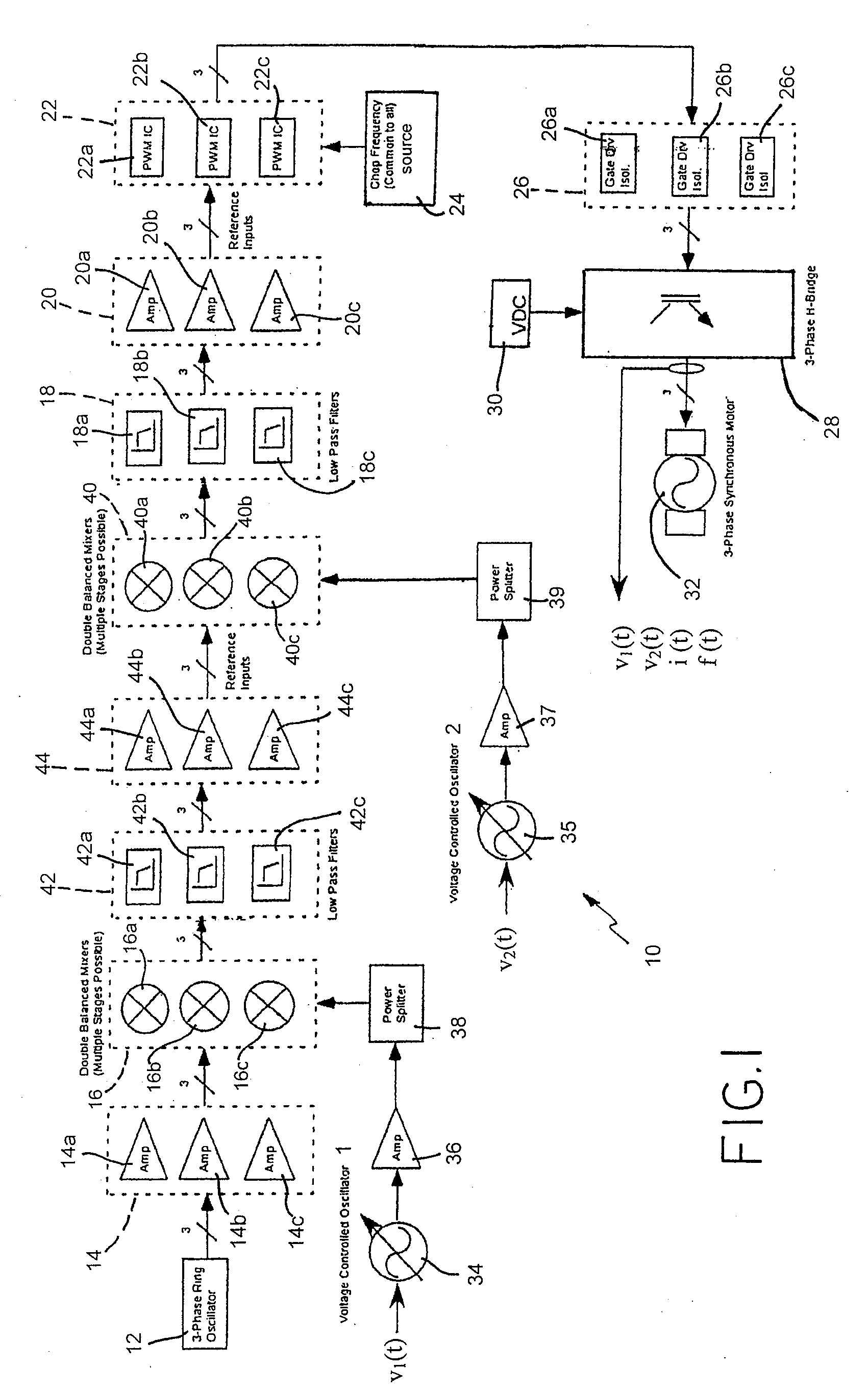
[0008]Referring to FIG. 1, there is shown a combined schematic and block diagram of a multi-phase, multi-frequency controller 10 which is particularly adapted for use with an electric motor 32 in accordance with the present invention.

[0009]Multi-phase, multi-frequency controller 10 includes a 3-phase ring oscillator 12 which provides 3 separate output reference signals which are offset in phase from one another by 120°. While described primarily in terms of a 3-phase controller, the present invention is not limited to the use of 3-phase signals, but will operate equally as well with virtually any number of phase offset signals covering the full 360° of motor rotation. Each of the three output reference signals from the 3-phase ring oscillator 12 is provided to one of three respective amplifiers 14a, 14b and 14c in a first amplification stage 14. The amplified output signals from amplifiers 14a, 14b and 14c are each provided to a respective double balanced mixer 16a, 16b and 16c in a...


PUM


Abstract

Reference signals are combined with a chop frequency signal in a pulse width modulator (PWM) to provide plural inputs to a multi-phase H-bridge amplifier. Also provided to the bridge amplifier is a high voltage DC input which is converted by the pulsed inputs to the bridge amplifier to a variable AC voltage for driving a motor. The AC drive voltage is also provided to a variable frequency voltage-controlled oscillators (VCOs) in a feedback arrangement, with the variable frequency VCO outputs heterodyned with each of plural outputs of a multi-phase ring oscillator to provide plural baseband signals having a constant phase relationship at a high frequency. The baseband signals form the aforementioned reference signals provided to the PWM in the feedback arrangement with closed loop control and frequency and phase discrimination using phase lock loop techniques for synchronous motor control over a range of DC-100 kHz with 0-25 MHz VCOs.

Description

FIELD OF THE INVENTION[0001]This invention relates generally to a multi-phase, multi-frequency controller employing frequency conversion and feedback control for providing a precisely controlled AC output voltage for driving a device such as an electric motor.BACKGROUND OF THE INVENTION[0002]Synchronous motors are commonly used in industrial power applications to generate AC power. A synchronous AC induction motor is comprised of a stator and a rotor. The stator assembly is typically comprised of steel laminations shaped to form poles, with copper wires wound around these poles to form primary windings connected to a voltage source for producing a rotating magnetic field. A rotor assembly is typically comprised of laminations formed around a steel shaft core, with radial slots disposed around the laminations' periphery having rotor bars in the form of conductors shorted at the ends disposed parallel to the steel shaft core. Torque within the AC induction motor is developed by the in...

Claims


Application Information

Patent Timeline
Patent Type & Authority Applications(United States)
IPC IPC(8): H02P6/08
CPCH02P6/001H02P6/34
Inventor GONDER, JOHN F.
Owner THE BOEING CO
Why Eureka
Try Eureka