High-effect cross flow washing pool
A cross-flow, high-efficiency technology, applied in the separation of dispersed particles, chemical instruments and methods, and the use of liquid separators, etc., can solve the problems of imperfect water quality monitoring systems, difficult cleaning of equipment, combined use of equipment, etc. Small area, long service life and water saving effect
- Summary
- Abstract
- Description
- Claims
- Application Information
AI Technical Summary
Problems solved by technology
Method used
Image

Examples
Embodiment 1
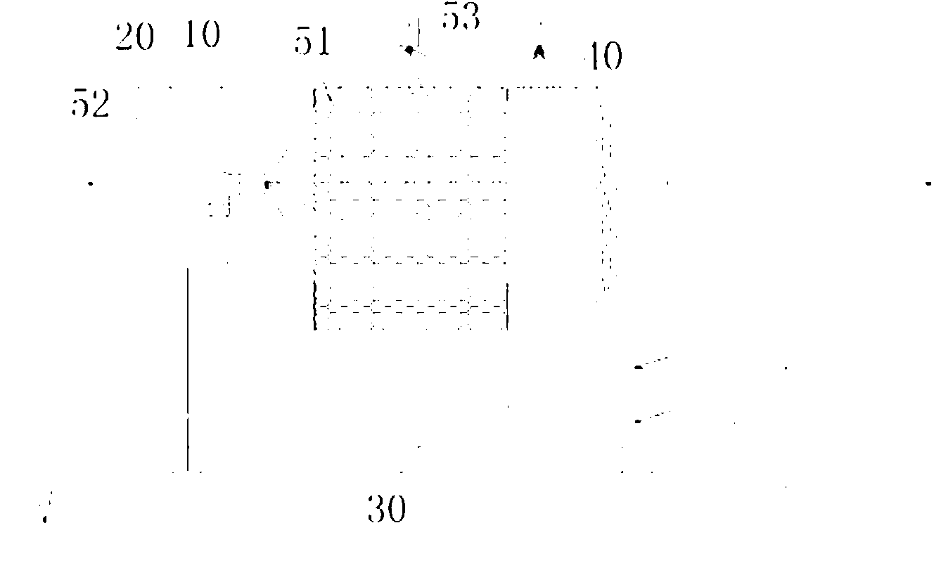
[0023] Such as figure 1 As shown, a high-efficiency cross-flow washing pool includes a box body 10. A purification cavity 20 penetrating from front to back is arranged in the box body 10. The front end and rear end of the box body 10 are respectively provided with Gas inlet and gas outlet, the purification cavity 20 is provided with a cross-flow exhaust gas treatment system 50, the cross-flow exhaust gas treatment system 50 is filled with polypropylene multi-faceted hollow ball filler 51 in the purification cavity 20 and used to The front spray system 52 and the upper spray system 53 are composed of the polypropylene multi-faceted hollow ball packing 51 spraying the purification liquid. The front spray system 52 is arranged on the front side of the polypropylene multi-face hollow ball packing 51, and the upper spray system 53 is arranged on Above the polypropylene multifaceted hollow ball filler 51 , a water pool 30 is arranged below the purification cavity 20 of the box body ...
Embodiment 2
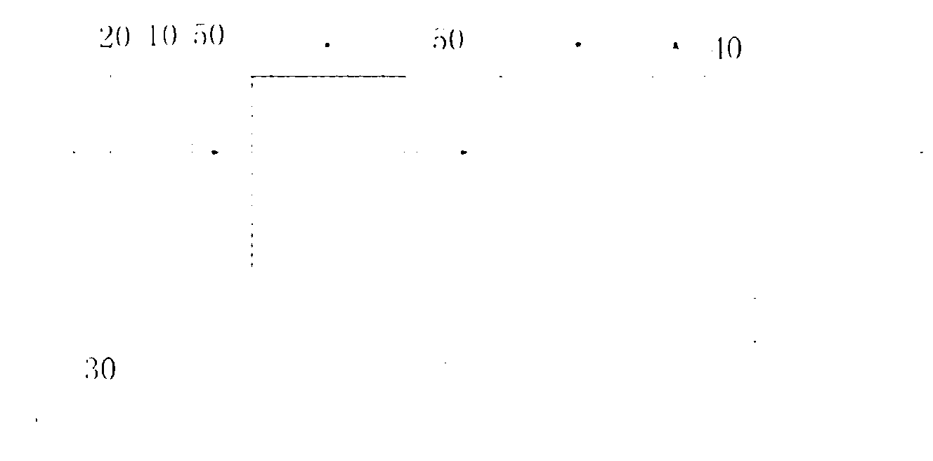
[0026] Such as figure 2 As shown, the difference between this embodiment and Embodiment 1 is that two cross-flow exhaust gas treatment systems 50 are arranged in the purification cavity 20. front side.
[0027] A cross-flow exhaust gas treatment system 50 can greatly reduce the content of larger particles (>=200um) and odor molecules in the exhaust gas. The second cross-flow exhaust gas treatment system 50 can further remove small particles (0.5-200um) and residual odor molecules in the exhaust gas. After passing through the two-stage treatment unit, the concentration of particulate matter and peculiar smell in the exhaust gas is greatly reduced, and after being treated by the gas-liquid separation device 40, the emission can reach the standard.
Embodiment 3
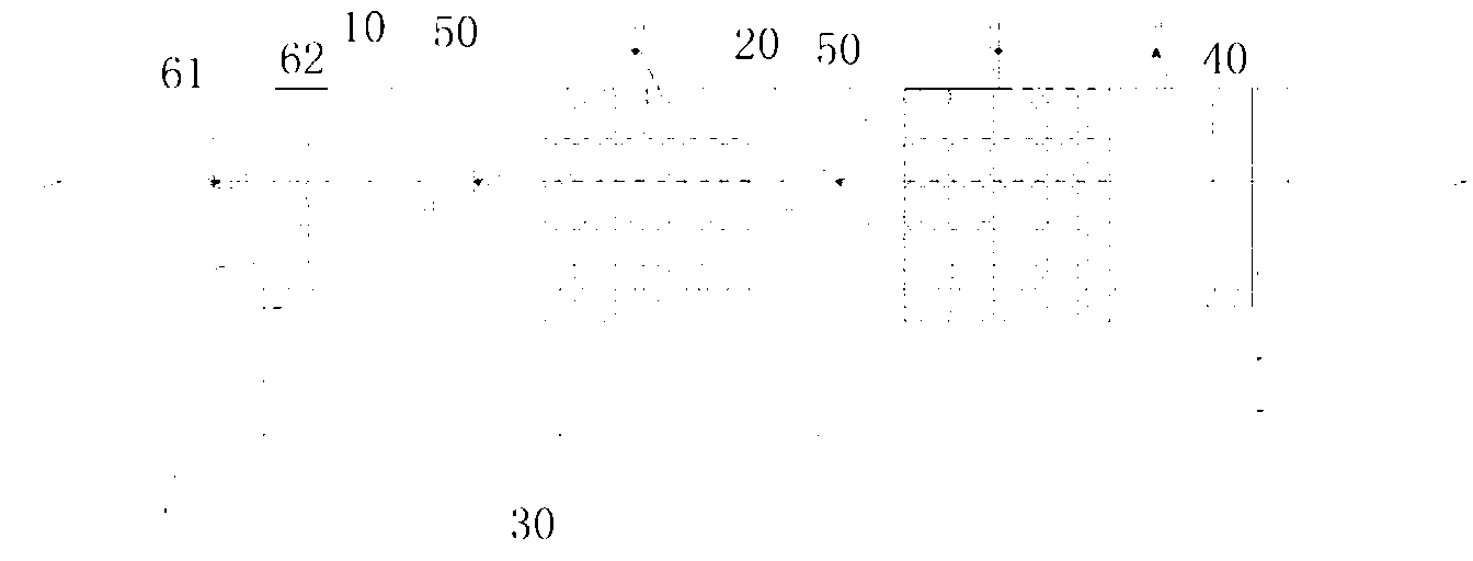
[0029] Such as image 3 As shown, the difference between this embodiment and Embodiment 2 is that the purification cavity 20 is provided with a convective exhaust gas treatment system 60 on the front side of the two cross-flow exhaust gas treatment systems 50, and the convective exhaust gas treatment system 60 is composed of gas-liquid The separation device 62 and the convective circulation spray device 61 arranged in front of the gas-liquid separation device 62 and spraying the purified liquid forward are constituted. The gas-liquid separation device 62 of the convective exhaust gas treatment system 60 is also composed of several corrugated partitions arranged obliquely.
[0030] During operation, the exhaust gas is firstly treated by the convective exhaust gas treatment system 60 . The convective circulation spraying device 61 sprays forward and is opposite to the flow direction of the exhaust gas. The droplets collide with, intercept and condense the particles in the exhau...
PUM
| Property | Measurement | Unit |
|---|---|---|
| diameter | aaaaa | aaaaa |
Abstract
Description
Claims
Application Information