Automobile urea box and forming method thereof

A molding method and urea tank technology, applied in mechanical equipment, engine components, machines/engines, etc., can solve the problem of difficulty in controlling the uniformity of the wall thickness of the box body, the small volume of the Adblue storage box for vehicles, and the flying of raw material surplus Edge and other issues, to achieve the effect of saving raw materials, shortening the production cycle, and good firmness

Active Publication Date: 2013-04-24
YAPP AUTOMOTIVE PARTS
View PDF4 Cites 5 Cited by
  • Summary
  • Abstract
  • Description
  • Claims
  • Application Information

AI Technical Summary

Problems solved by technology

The SCR box produced by blow molding process is firstly costly. The price of a blow molding equipment is more than ten times that of an injection molding equipment, which increases the equipment amortization of each box; secondly, Adblue for vehicles The volume of the storage box is small, and it is not easy to control the wall thickness and uniformity of the box body by blow molding process, which often leads to excessive wall thickness and waste of raw materials; a large amount of surplus flash of raw materials is easy to appear around the blow molding products, A lot of raw materials are wasted, and the blow molding process is used, and the built-in components in the box are limited. For example, the design of the anti-wave plate for large parts is limited to the diameter of the outer box in the blow molding process

Method used


Image

  • Automobile urea box and forming method thereof
  • Automobile urea box and forming method thereof
  • Automobile urea box and forming method thereof

Examples


Embodiment 1

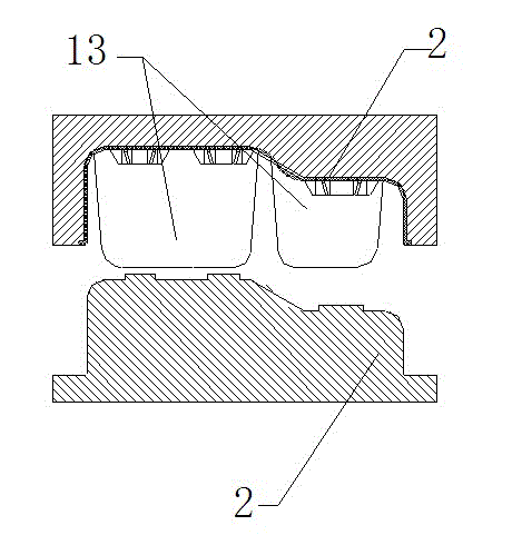
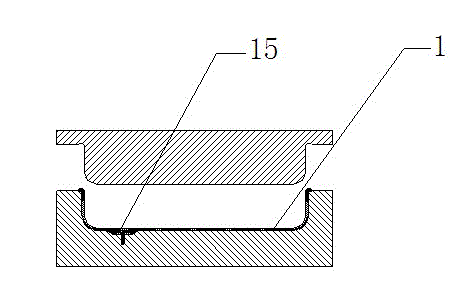
[0028] see figure 1 — Figure 6 , a method for forming an automotive urea tank, the method comprising the following steps, 1) producing an upper half shell 2 and a lower half shell 1 by an injection molding method, see figure 1 , 2 In the injection molding process, the anti-wave plate 13 and the assembly structure 16 of the surface parts of the box body can be injection molded together with the upper half shell 2, and the assembly screws 15 of the protection plate and the welding structure 21 of the sensor port can be injection molded together with the lower half shell 1 , the injection molding of the anti-wave plate 13 and the shell as a whole, firstly improves the degree of freedom in the design of the built-in components of the box, that is, the setting of the built-in components is no longer limited to the outer diameter of the box, and secondly reduces the follow-up welding work. 2) After the upper and lower half-shells are formed, assemble the built-in parts of the upp...

Embodiment 2

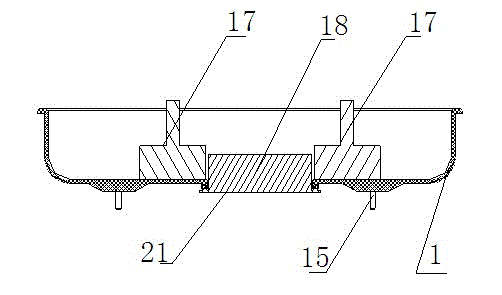
[0030] see image 3, as an improvement of the present invention, during the process of welding the built-in pump assembly 18 of the sensor port welding structure 21 to the lower half-shell 1, a baffle 17 is set on the inner wall of the lower half-shell 1, and the baffle is taken out after welding . Weld the pump assembly to the lower half shell, because the welding process needs to apply a large pressure to ensure the fusion between the two welded bodies, and the pressure is too high to easily deform the box, so the inner wall of the lower half shell Place the corresponding baffle plate 17. The baffle plate is made of metal material, thereby ensuring the stability of the shape of the shell under heavy pressure. The structural shape of the baffle plate matches the structure of the inner wall of the box. The baffles 17 are symmetrically arranged on both sides of the pump assembly 18. This method is not only simple and effective, but also saves a lot of raw materials. Traditi...

Embodiment 3

[0031] Example 3 : In step 1, the upper half shell 2 and the lower half shell 1 are produced by injection molding. In the injection molding process, the box body surface parts assembly structure 16 is injection molded together with the upper half shell 2, the anti-wave plate 13, the protective plate The assembly screw 15, the welded structure of the sensor port and the lower half shell 1 are injection molded together. The remaining steps and advantages are exactly the same as in Embodiment 1.


PUM


Abstract

The invention relates to an automobile urea box and a forming method thereof. The automobile urea box and the forming method are characterized in that the forming method comprises the steps of (1) using an injection molding method to produce an upper half casing and a lower half casing; (2) assembling built-in parts of the upper half casing and the lower half casing after the upper half casing and the lower half casing are formed; (3) welding the assembled upper half casing and the assembled lower half casing integrally; and (4) assembling components and parts on the surfaces of the upper half casing and the lower half casing. By means of the forming method, the design free degree of the built-in parts of a box body can be improved, a large amount of raw materials can be saved, the automobile urea box is simple in structure and good in soundness, the production efficiency is improved, and a production period is shortened.

Description

technical field [0001] The invention relates to an exhaust system of a diesel automobile, in particular to an automobile urea tank and a forming method thereof. Background technique [0002] In order to protect the air quality of the environment, countries around the world have successively issued various regulations and policies to control automobile exhaust. The automobile industry has also paid more and more attention to the environmental pollution caused by exhaust emissions. Various regulations that are demanding and limit the value of pollutant emissions compete with each other. In particular, the emission requirements for nitrogen oxides in vehicle exhaust are more stringent. With the implementation of EURO 6, the emission limit of nitrogen oxides will reach 0.07g / km. To this end, major OEMs have introduced different new technologies for reducing exhaust emissions, which mainly include Selective Catalytic Reduction (SCR) technology. Utilize this technology to spray ...

Claims


Application Information

Patent Timeline
IPC IPC(8): F01N3/28B29C45/00B29C65/02
CPCY02A50/20
Inventor 孙岩姜林刘亮朱海洋陈新华薛晴郑光松
Owner YAPP AUTOMOTIVE PARTS
Why Eureka
Try Eureka