
Optical module of motor vehicle lightning device

A lighting device and optical module technology, which is applied in the field of optical modules, can solve the problems of dazzling traffic participants, complicated layout, positioning and orientation, etc., and achieve the effects of optimizing heat transfer, improving cooling effect, and reducing manufacturing and installation costs

Inactive Publication Date: 2013-04-24
AUTOMOTIVE LIGHTING REUTLINGEN GMBH
View PDF6 Cites 4 Cited by
  • Summary
  • Abstract
  • Description
  • Claims
  • Application Information

AI Technical Summary

Problems solved by technology

In the switched-on state, the light emitted directly by the LED may dazzle oncoming traffic participants
In addition, complex arrangement, positioning and orientation of the optical cell library in terms of LED-cooling body-unit is required in the mounting frame of the light module
In the light module known from this document no shutter is provided

Method used


Image

  • Optical module of motor vehicle lightning device
  • Optical module of motor vehicle lightning device
  • Optical module of motor vehicle lightning device

Examples


Embodiment Construction

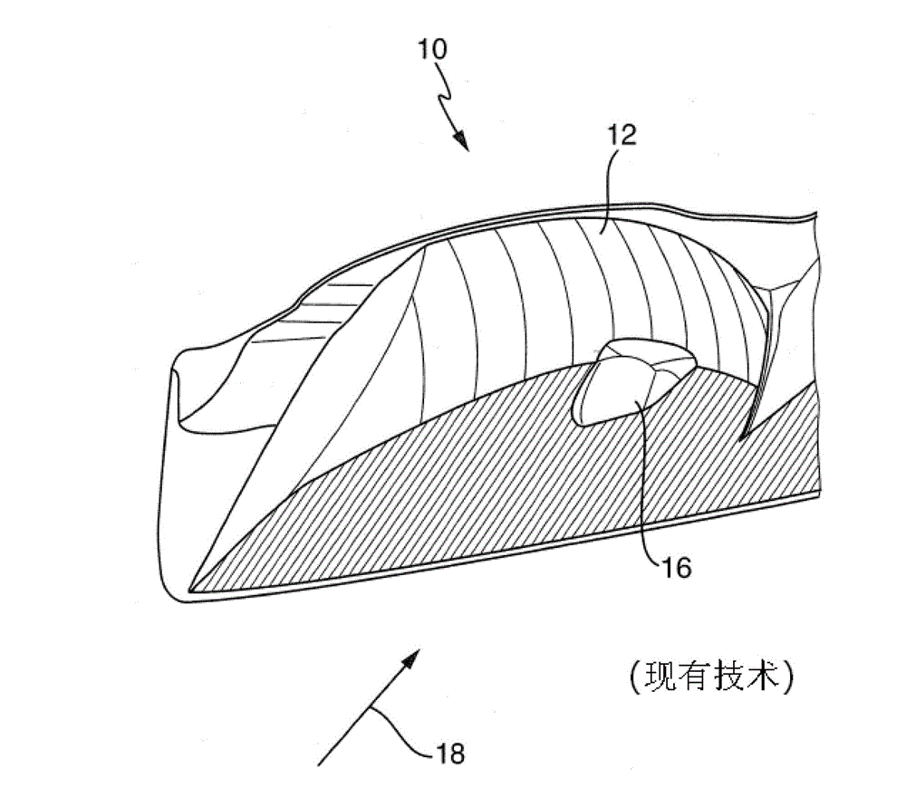
[0038] figure 1 A part of a lighting system of a motor vehicle known from the prior art is shown. The lighting device is designed here as a motor vehicle headlight. The known light module 10 of the headlight has a raised reflector 12 as the main optical unit, which is equipped with at least one light source designed as a semiconductor light source, in particular a light-emitting diode. The light emitting diode is in figure 1 It cannot be seen because it is arranged below the visor 16 so as not to be visible from the outside of the headlights in the direction of sight 18 . Furthermore, the visor 16 prevents the light emitted by the light-emitting diodes from leaving the headlights directly, ie without being reflected on the reflector 12 . The visor 16 is arranged in the vicinity of the light source so that it fulfills the functions described above. Furthermore, the shutter 16 is preferably arranged outside the focal area of ​​the main optical unit 12 .

[0039] The light d...


PUM


Abstract

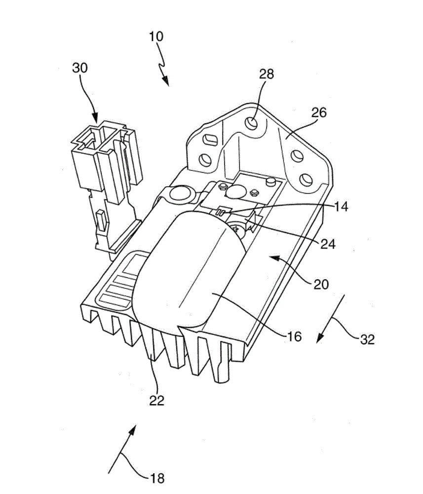
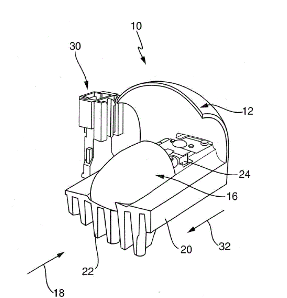
The invention relates to an optical module (10) of a motor vehicle lightning device. The optical module (10) has: at least one semiconductor light source (14) for emitting light; a main optical unit (12) for constricting at least one part of the light emitted by the at least one semiconductor light source (14); a light shield (16) subject to the at least one semiconductor light source (14); and a cooling piece (20) in at least indirect thermal contact with the at least one semiconductor light source (14). In order to fabricate the optical module (10) simply and cost-effectively, at least one part of the light shield (16) is suggested to be an element of integration of the cooling piece (20).

Description

technical field [0001] The invention relates to a light module of a lighting device of a motor vehicle. The optical module has: at least one semiconductor light source for emitting light; a main optical unit for at least a part of the bundle of light emitted by the at least one semiconductor light source; a light shield belonging to the at least one semiconductor light source; cooling body in at least indirect thermal contact with the at least one semiconductor light source. Background technique [0002] Various lighting devices for motor vehicles are known in the prior art. Therefore, it is divided into headlights and headlights. The headlights are only set on the front part of the vehicle. In addition to achieving traffic safety by making the vehicle visible to other road users, it is also used, for example, in the form of night lights, high beams or fog lights, or in the form of any other headlight functions (such as adaptive light distribution) to illuminate the lane...

Claims


Application Information

Patent Timeline
IPC IPC(8): F21S8/10F21V1/00F21V7/00F21V29/00F21W101/02F21Y101/02F21W107/10
CPCF21S48/1305F21S48/215F21S48/147F21S48/255F21S48/142F21S48/1159F21V11/00F21V29/00F21S48/328F21S48/232F21S41/148F21S41/39F21S41/435F21S41/47F21S43/14F21S43/37F21S43/51F21S45/47
Inventor 迈克尔·迪尔菲利普·席廷迈克尔·马尔
Owner AUTOMOTIVE LIGHTING REUTLINGEN GMBH
Learn More