Condensation water circulating system of power station

A technology for condensed water and water circulation, applied in chemical instruments and methods, liquid degassing, separation methods, etc., can solve the problems of waste of manufacturing cost and operating cost, need to be optimized, poor speed regulation performance, etc., to reduce throttling loss, Best energy-saving effect, the effect of eliminating energy consumption

Active Publication Date: 2013-04-24
CHINA SHENHUA ENERGY CO LTD +2
View PDF5 Cites 0 Cited by
  • Summary
  • Abstract
  • Description
  • Claims
  • Application Information

AI Technical Summary

Problems solved by technology

The piping arrangement of the condensate circulation system in the prior art is suitable for systems with constant-speed drive condensate pumps or condensate pumps with poor speed regulation performance
When the condensate pump is im

Method used


Image

  • Condensation water circulating system of power station
  • Condensation water circulating system of power station
  • Condensation water circulating system of power station

Examples


Example Embodiment

[0028] The specific embodiments of the present invention will be described in detail below with reference to the accompanying drawings. It should be understood that the specific embodiments described herein are only used to illustrate and explain the present invention, and not to limit the present invention.

[0029] reference Figure 5 with Image 6 , The present invention provides a condensate circulation system for a power plant. The condensate circulation system includes a condensate pump unit 4, and a condensate pump 43 in the condensate pump unit 4 drives the condensate to flow to the low-pressure heater unit 2. The condensed water is heated in the low-pressure heater unit 2 and enters the subsequent deaerator. The water outlet of the low-pressure heater unit 2 is connected to a deaerator water tank 1, and the deaerator water tank 1 supplies water to the deaerator to remove the oxidizing gas in the condensate and ensure the quality of boiler feed water.

[0030] More specif...


PUM


Abstract

The invention discloses a condensation water circulating system of a power station. The condensation water circulating system comprises a condensation water pump unit (4), a deaerator water tank (1), a low-pressure heater unit (2), a recycling branch (3), a condensation water supplement water tank (6), and a condensation water recovering branch (7). A control module which responds to a water level signal of the deaerator water tank to adjust rotating speed of three condensation water pumps (43) is arranged on a frequency converter. A deaerator water level adjusting gate and a deaerator water level separating gate are arranged on a low-pressure heater bypass pipe. The invention further discloses another condensation water circulating system of the power station. The another condensation water circulating system comprises a condensation water pump unit, a deaerator water tank, a low-pressure heater unit, a condensation water supplement water tank and a condensation water recovering branch, wherein the a control module which responds to a water level signal of the deaerator water tank to adjust rotating speed of three condensation water pumps is arranged on a frequency converter, and a deaerator water level adjusting gate and a deaerator water level separating gate are arranged on a low-pressure heater bypass pipe. The condensation water circulating systems are used for simplifying pipelines of condensation water.

Description

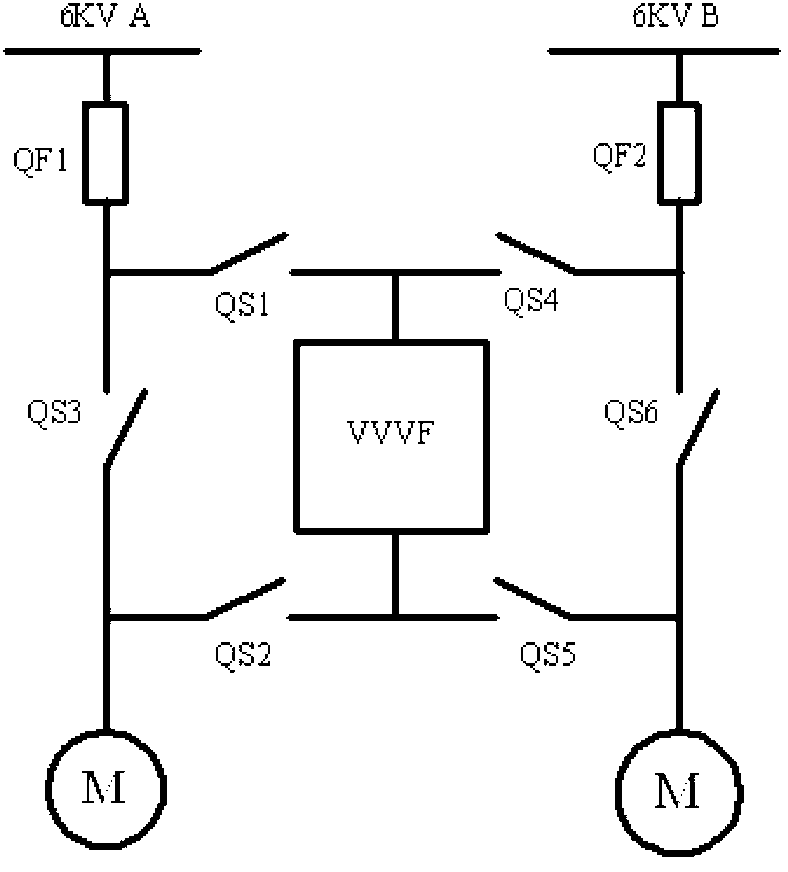
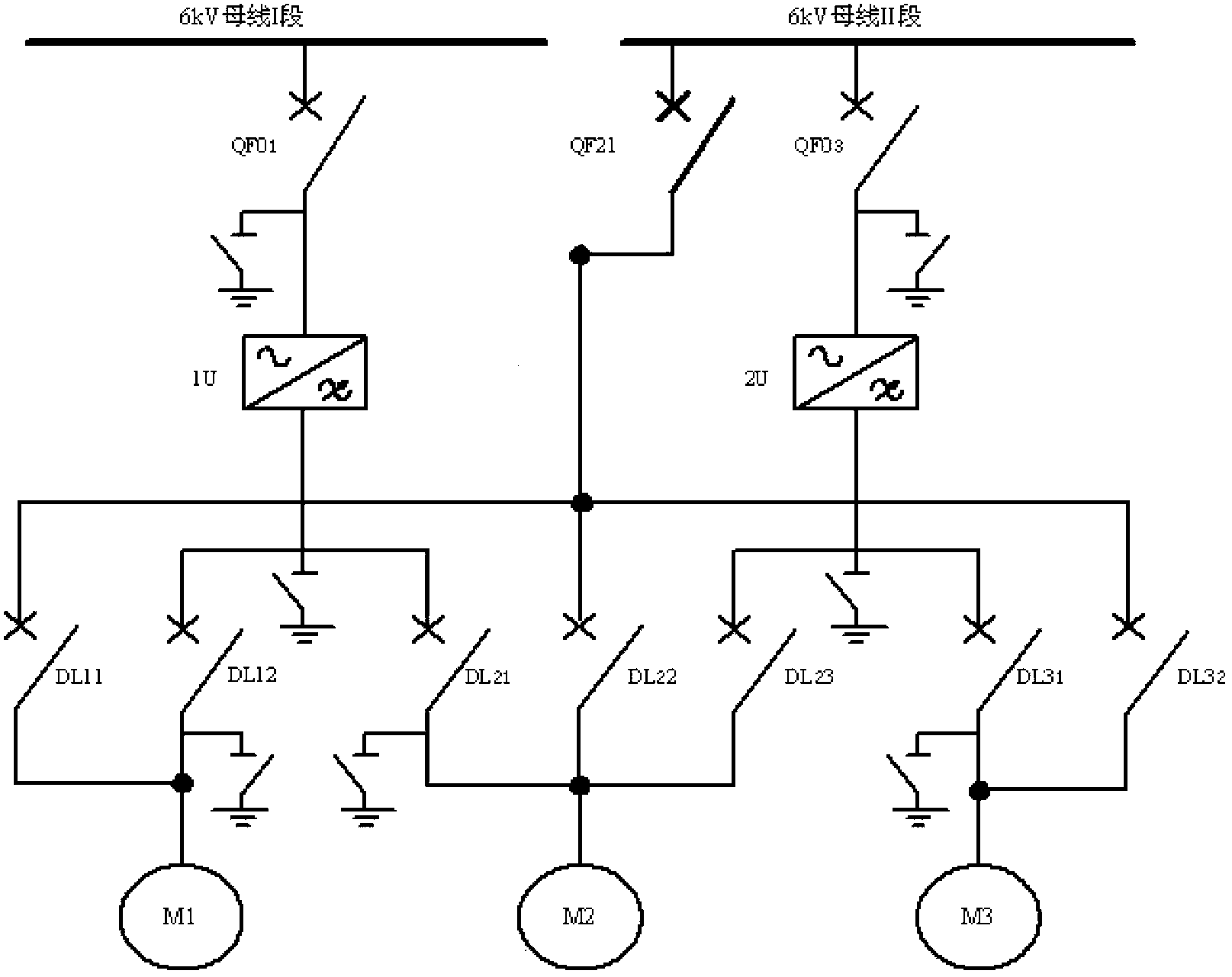
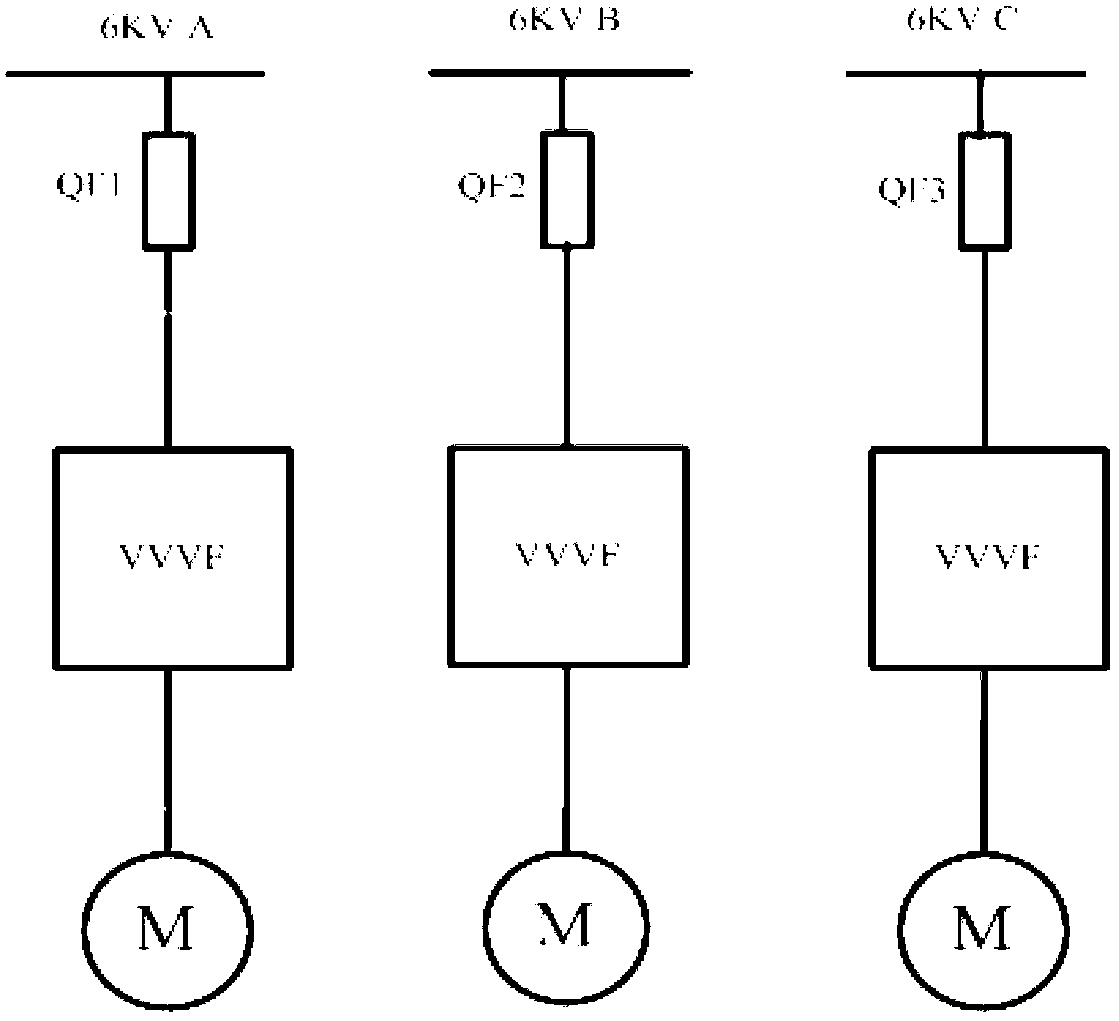
technical field [0001] The invention relates to the field of thermal power generation, in particular to a condensate circulation system of a power plant. Background technique [0002] Most of the condensate pumps of large thermal power generating units in the prior art have been improved to be driven by frequency converters. The inverter drive has good start-up characteristics and speed regulation performance, and can effectively control the operation mode of the condensate pump, thereby accurately controlling the level of the condensate water and the flow rate. [0003] attached figure 1 to attach image 3 It is the three main electrical system wiring diagrams of the frequency converter and the condensate pump. Among them, attached figure 1 Shown in is the variable frequency drive mode of 2×100% flow condensate pumps, one for two, the maximum flow of each condensate pump is 100% of the maximum flow of the condensate circulation system, and the two condensate pumps are u...

Claims


Application Information

Patent Timeline
IPC IPC(8): F22D1/50
Inventor 岳建华李勐岳涛张强
Owner CHINA SHENHUA ENERGY CO LTD
Why Eureka
Try Eureka