
MOS transistor and its manufacturing method

A technology of a MOS transistor and a manufacturing method, which are applied in the field of MOS transistors and their manufacturing, can solve the problems of depression on the upper surface of a metal gate, the inability of the first dielectric layer 10 to be flush, and affecting the gate resistance value, etc.

Active Publication Date: 2016-03-16
SEMICON MFG INT (SHANGHAI) CORP
View PDF4 Cites 0 Cited by
  • Summary
  • Abstract
  • Description
  • Claims
  • Application Information

AI Technical Summary

Problems solved by technology

Polysilicon gates have the following problems: increase in the effective thickness of the gate insulating film due to the gate loss phenomenon, threshold voltage due to the phenomenon of dopant permeation from the P+ or N+ polysilicon gate to the substrate and changes in dopant distribution changes, etc.
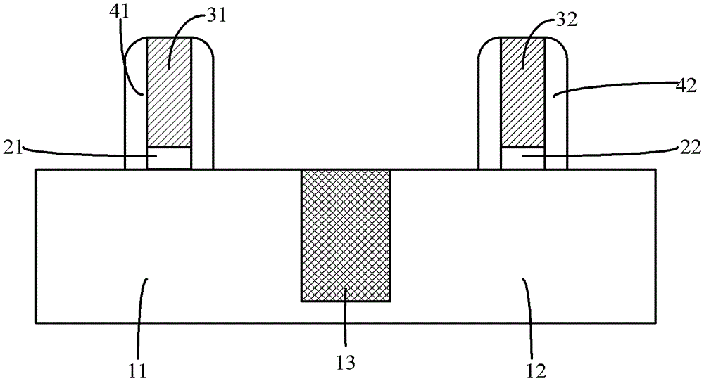
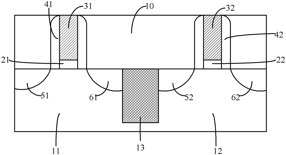
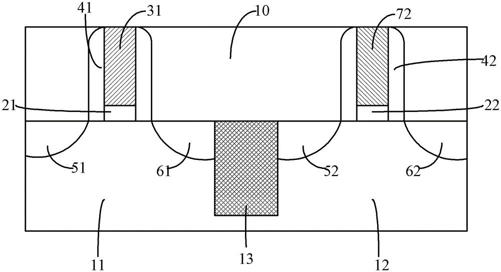
[0010] However, in the above technology, in the process of forming the first metal gate 71 or the second metal gate 72, the upper surface of the first metal gate 71 and the upper surface of the first dielectric layer 10 need to be connected by CMP. flush or make the upper surface of the second metal grid 72 flush with the upper surface of the first dielectric layer 10, and the area of ​​the upper surface of the first metal grid 71 or the second metal grid 72 is relatively larger than that of the first dielectric layer. The area of ​​the upper surface of the layer 10 is relatively small, so that the upper surface of the first metal grid 71 or the upper surface of the second metal grid 72 has a recess, which cannot be completely flush with the upper surface of the first dielectric layer 10, and eventually Affects gate resistor value
[0011] Similarly, in the process of fabricating the metal gate of NMOS transistors or PMOS transistors using the gate-last process, there is also the defect that the upper surface of the metal gate is recessed

Method used


Image

  • MOS transistor and its manufacturing method
  • MOS transistor and its manufacturing method
  • MOS transistor and its manufacturing method

Examples


Embodiment 1

[0065] refer to Figure 7 As shown, this embodiment provides a method for manufacturing an NMOS transistor, including:

[0066] Step S11, providing a semiconductor substrate, sequentially forming a gate dielectric layer and a dummy gate electrode on the semiconductor substrate, and forming source / drain regions in the semiconductor substrate;

[0067] Step S12, forming a first dielectric layer on the semiconductor substrate, the upper surface of the first dielectric layer being flush with the upper surface of the dummy gate electrode;

[0068] Step S13, removing the dummy gate electrode, forming a first via hole, forming a second via hole in the first dielectric layer corresponding to the source region, and forming a third via hole in the first dielectric layer corresponding to the drain region hole;

[0069] Step S14, respectively filling the sidewalls and bottoms of the first through hole, the second through hole and the third through hole in sequence with a work function m...

Embodiment 2

[0097] This embodiment provides a method for manufacturing a PMOS transistor, including:

[0098] Provide semiconductor substrates;

[0099] sequentially forming a gate dielectric layer, dummy gate electrodes, and spacers surrounding the gate dielectric layer and dummy gate electrodes on the semiconductor substrate;

[0100] Forming source / drain regions in the semiconductor substrate by using the gate dielectric layer, dummy gate electrodes and sidewalls as masks;

[0101] forming a first dielectric layer on the semiconductor substrate, the upper surface of the first dielectric layer being flush with the upper surface of the dummy gate electrode;

[0102] removing the dummy gate electrode, forming a first through hole, forming a second through hole in the first dielectric layer corresponding to the source region, and forming a third through hole in the first dielectric layer corresponding to the drain region;

[0103] Filling the sidewalls and bottoms of the first through ho...

Embodiment 3

[0116] This embodiment provides a method for manufacturing a CMOS transistor, including:

[0117] A semiconductor substrate is provided, the semiconductor substrate includes a PMOS transistor region and an NMOS transistor region, a first gate dielectric layer and a first dummy gate electrode are sequentially formed on the NMOS transistor region, and a first dummy gate electrode is formed in the NMOS transistor region. A source / drain region; a second gate dielectric layer and a second dummy gate electrode are sequentially formed on the PMOS transistor region, and a second source / drain region is formed in the PMOS transistor region. Forming a CMOS transistor including a dummy gate electrode is well known to those skilled in the art and will not be repeated here.

[0118] A first dielectric layer is formed on the semiconductor substrate, and the upper surface of the first dielectric layer, the upper surface of the first dummy gate electrode and the upper surface of the second dum...


PUM


Abstract

Disclosed are a metal oxide semiconductor (MOS) transistor and a manufacturing method thereof. The manufacturing method includes the steps of supplying a semiconductor substrate; forming a dummy gate electrode on the semiconductor substrate; forming a source / drain region inside the semiconductor substrate; forming a first dielectric layer on the semiconductor substrate, wherein the upper surface of the first dielectric layer is level with the upper surface of the dummy gate electrode; removing the dummy gate electrode to form a first through hole, forming a second through hole in the first dielectric layer corresponding to the source region, and forming a third through hole in the first dielectric layer corresponding to the drain region; and padding work function metal layers and metal layers respectively into the side walls of the first through hole, the second through hole and the third through hole in sequence so as to form a metal grid, a first contact plug and a second contact plug, wherein the upper surfaces of the metal grid, the first contact plug and the second contact plug are respectively level with the upper surface of the first dielectric layer. By means of the MOS transistor and the manufacturing method thereof, pits do not occur on the upper surface of the metal grid, and thus smoothness is achieved.

Description

technical field [0001] The invention relates to the field of integrated circuit manufacturing, in particular to a MOS transistor and a manufacturing method thereof. Background technique [0002] Heretofore, polysilicon gates, polysilicate gates, and the like have been used as gates in semiconductor devices. Polysilicon gates have the following problems: increase in the effective thickness of the gate insulating film due to the gate loss phenomenon, threshold voltage due to the phenomenon of dopant permeation from the P+ or N+ polysilicon gate to the substrate and changes in dopant distribution changes etc. There is also a problem that a conventional polysilicon gate cannot achieve a low resistance value on a line with a narrow width. [0003] In order to solve the above problems, the prior art provides a solution of replacing the polysilicon gate with a metal gate. At present, the method of preparing metal gates is commonly used as a manufacturing method introduced in US ...

Claims


Application Information

Patent Timeline
Patent Type & Authority Patents(China)
IPC IPC(8): H01L21/768H01L21/336H01L29/78H01L23/532
CPCH01L2924/0002
Inventor 平延磊
Owner SEMICON MFG INT (SHANGHAI) CORP
Learn More