
Prefabricated substation

A prefabricated substation and installation hole technology, which is applied in the direction of cooling/ventilation of power distribution substation, substation/switchgear, etc., can solve the problems of affecting work stability, shortening service life, deformation of door panels, etc., and achieves good protection and support effect , to ensure the stability of work, to enhance the effect of heat insulation performance

Active Publication Date: 2015-08-26
宁波燎原电器集团股份有限公司
View PDF3 Cites 0 Cited by
  • Summary
  • Abstract
  • Description
  • Claims
  • Application Information

AI Technical Summary

Problems solved by technology

[0003] The prefabricated substation of the prior art has the following defects: First, in some extremely high temperature areas such as deserts, the heat dissipation effect of the prefabricated substation of the prior art is still not ideal, and the heat generated by the distribution transformer in the housing is still unable to be dissipated in time. The temperature inside the shell is still high, and the continuous operation of the distribution transformer in a high-temperature environment will shorten its service life and cause a high failure rate; secondly, the door of the prefabricated substation is made of a thin steel plate about 2mm thick, and the thin steel plate Poor heat insulation performance, in the high temperature outdoor environment, it will also cause the temperature of the electrical components in the casing to be too high, affect the working stability, and even pose a safety hazard. Moreover, the door panel of the thin steel plate is easy to be deformed under external impact, which is harmful to the box body. The protection and support of the internal electrical components is insufficient; moreover, the grounding line is connected by multiple components, and there are many connection nodes. Cause safety accidents, so in the occasions with high safety and stability requirements and low fault tolerance rate requirements, the existing prefabricated substations cannot meet the safety requirements

Method used


Image

  • Prefabricated substation
  • Prefabricated substation
  • Prefabricated substation

Examples


Embodiment Construction

[0015] The present invention will be further described below in conjunction with the accompanying drawings and specific embodiments.

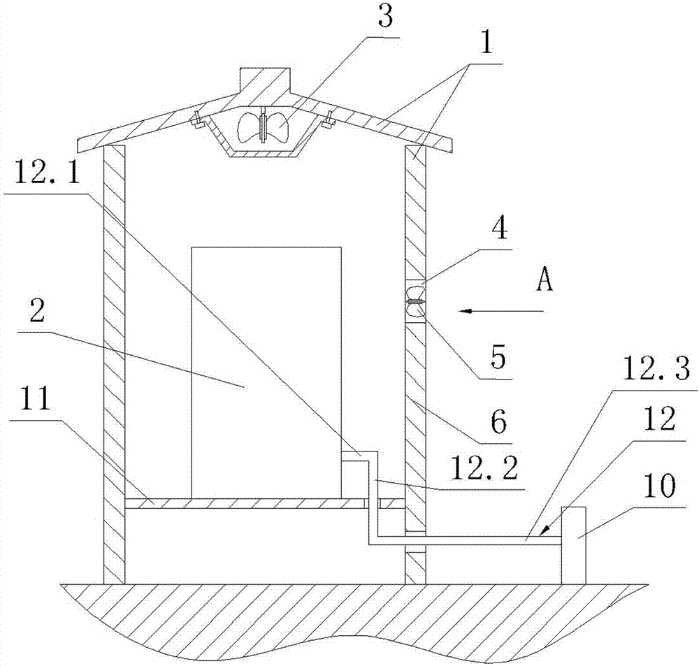
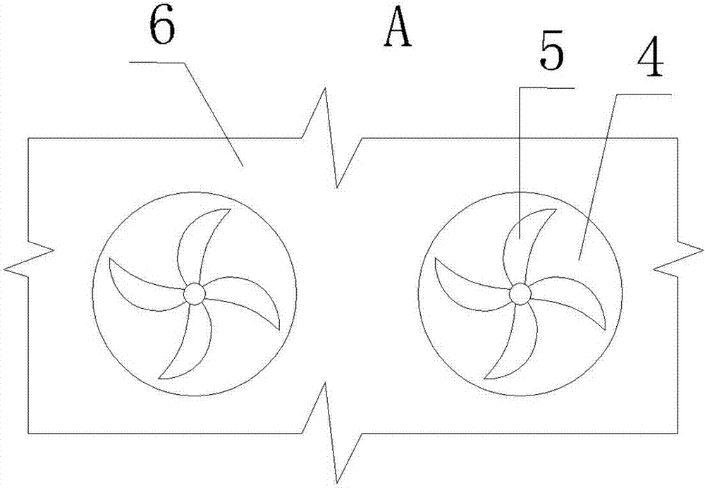
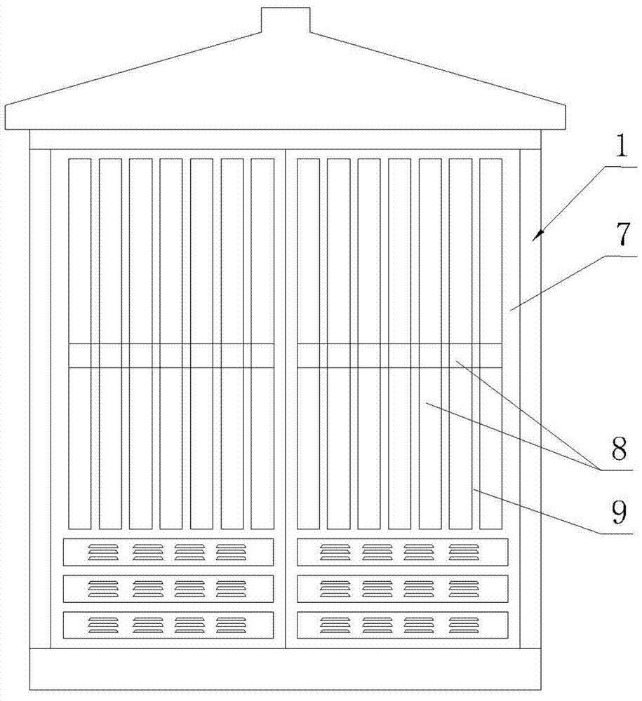
[0016] Such as figure 1 , figure 2 , image 3 As shown, the prefabricated substation of the present invention includes a housing 1 on which a door 7 made of steel plate is hinged, and a distribution transformer 2 is installed in the housing 1 . A first air suction and exhaust fan 3 is suspended from the top of the housing 1 , and the first air suction and exhaust fan 3 is located above the distribution transformer 2 . The side wall 6 of the housing is penetrated with mounting holes 4 , specifically, two mounting holes 4 are provided on the left side wall 6 of the housing, and a second suction and exhaust fan 5 is provided in each mounting hole 4 . The total area of ​​the two mounting holes 4 accounts for one percent of the surface area of ​​a single side wall 6 of the housing 1 . Such an area ratio can not only ensure effective heat dissip...


PUM


Abstract

The invention discloses a preassembled type transformer substation which comprises a shell body (1). The shell body (1) is in hinge joint with a door made of steel plates, a distribution transformer (2) is mounted in the shell body (1), and a first air suction extractor fan (3) is mounted on the top of the shell body (1) in an overhanging mode. The first air suction extractor fan (3) is located above the distribution transformer (2), mounting holes (4) are formed in the side wall (6) of the shell body (1) in a penetrating mode, and a second air suction extractor fan (5) is arranged on each mounting hole (4). Imitation wood plates are fixed on the outer surface of the door. The preassembled type transformer substation can not only strengthen a heat dissipation effect but also strengthen a heat insulation effect.

Description

technical field [0001] The invention relates to the field of power systems, in particular to a prefabricated substation. Background technique [0002] Prefabricated substation, as a ring network type or terminal type power transformation and distribution device, is widely used outdoors in residential quarters, industrial and mining enterprises, hotels, hospitals, airports, railways and other places. The prefabricated substation includes a shell and a grounding device. The shell is equipped with high-voltage switchgear, distribution transformers and low-voltage power distribution devices. A suction exhaust fan is suspended and fixed in the shell above the distribution transformer. On the bottom plate of the shell There is an air inlet, and the suction fan makes the air enter from the suction port, and then is discharged by the suction fan, and the heat generated by the distribution transformer is dissipated in the process of gas circulation and convection. The grounding devi...

Claims


Application Information

Patent Timeline
Patent Type & Authority Patents(China)
IPC IPC(8): H02B7/06H02B1/56
Inventor 林先明王锡痒
Owner 宁波燎原电器集团股份有限公司
Learn More