Novel voltage reduction type bridgeless Cuk power factor correction (PFC) circuit

A new type of power factor correction technology, applied in the direction of output power conversion device, AC power input conversion to DC power output, electrical components, etc., can solve the problem of low conversion efficiency, achieve low switching loss, high efficiency without electrical isolation, The effect of good EMI characteristics

Inactive Publication Date: 2014-11-05
FUZHOU UNIV
View PDF4 Cites 1 Cited by
  • Summary
  • Abstract
  • Description
  • Claims
  • Application Information

AI Technical Summary

Problems solved by technology

[0004] At present, the Boost circuit has been widely used in the industry because of its continuous input current, simple topology, high conversion efficiency, grounded power switch tube, and easy control. Insufficiencies such as low time-to-time conversion efficiency; adopting a step-down PFC scheme can improve the deficiency of Boost PFC in some occasions

Method used


Image

  • Novel voltage reduction type bridgeless Cuk power factor correction (PFC) circuit
  • Novel voltage reduction type bridgeless Cuk power factor correction (PFC) circuit
  • Novel voltage reduction type bridgeless Cuk power factor correction (PFC) circuit

Examples


Embodiment Construction

[0030] In order to make the object, technical solution and advantages of the present invention clearer, the present invention will be further described in detail below through specific embodiments and related drawings.

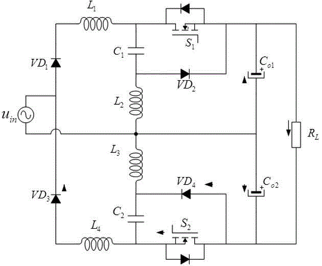
[0031] See figure 1 , figure 1It is a schematic diagram of circuit connection of a specific embodiment of the present invention. This embodiment provides a novel step-down bridgeless Cuk power factor correction PFC converter, including an input AC voltage source, characterized in that: one end of the input AC voltage source is connected to the anode of a diode VD1 and the cathode of a diode VD3 The cathode of the diode VD1 is connected to one end of an inductor L1; the other end of the inductor L1 is connected to the drain of a power switch S1 and one end of an intermediate capacitor C1; the gate of the power switch S1 is connected to a first A PWM control signal, the source is connected to the positive pole of an output electrolytic capacitor Co1 and one en...


PUM


Abstract

The invention relates to a novel voltage reduction type bridgeless Cuk power factor correction (PFC) circuit. The novel voltage reduction type bridgeless Cuk PFC circuit comprises a power switch tube S1, a power switch tube S2, a diode D1, a diode D2, a diode D3, a diode D4, a middle capacitor C1, a middle capacitor C2, an output electrolytic capacitor Co1, an output electrolytic capacitor Co2, an electrical inductance L1, an electrical inductance L2, an electrical inductance L3 and an electrical inductance L4. The novel voltage reduction type bridgeless Cuk PFC circuit is constructed, and functions of efficiency and high power factor and stable direct-current output and the like are achieved.

Description

technical field [0001] The invention relates to a novel step-down bridgeless Cuk power factor correction PFC converter, in particular to a low-ripple single-phase power factor correction circuit with high efficiency at both full load and light load. Background technique [0002] Power electronic devices such as switching power supplies have been widely used in power systems, industries, transportation, and households, and the resulting problems of lower input power factor and harmonic pollution on the grid side are becoming more and more serious. High-efficiency power factor correction converters have become the main means of suppressing harmonic pollution. [0003] Power factor correction converters can be divided into passive power factor correction converters and active power factor correction converters. Active power factor correction converters can obtain stable output voltage and high power factor because of their small size and light weight. Used in power electronic ...

Claims


Application Information

Patent Timeline
Patent Type & Authority Patents(China)
IPC IPC(8): H02M7/217H02M1/42
CPCY02B70/126Y02B70/10Y02P80/10
Inventor 林维明黄超
Owner FUZHOU UNIV
Why Eureka
Try Eureka