
An Axial-Radial Reactor Structure for Sulfur Tolerance Shift Process

A sulfur-resistant shift and reactor technology, applied in chemical instruments and methods, chemical/physical processes, etc., can solve the problems that the reactor volume cannot be fully utilized, the equipment processing precision is high, and the axial effect is not obvious. To achieve the effect of reducing equipment weight, improving utilization rate and reducing equipment investment

Active Publication Date: 2015-10-28
SINOPEC NINGBO ENG +2
View PDF5 Cites 1 Cited by
  • Summary
  • Abstract
  • Description
  • Claims
  • Application Information

AI Technical Summary

Problems solved by technology

The reactor simply connects the axial reactor and the radial reactor together up and down. The catalyst in the reactor is divided into axial and radial loading, and the top of the axial section has holes, but the outer frame of the catalyst and the central tube There are no holes in the axial section. This design is basically consistent with the form of a radial reactor. A very small amount of fluid will enter the catalyst bed through the channel at the top of the axial direction, and the axial effect is not obvious; in addition, the outer frame of the catalyst is directly connected to the cylinder. The temperature of the entire reactor cylinder is still very high, not only the equipment material is high, but also the processing accuracy of the equipment is high. At the same time, there are still catalyst seals that do not participate in the reaction, and the volume of the entire reactor remains the same. underutilized

Method used


Image

  • An Axial-Radial Reactor Structure for Sulfur Tolerance Shift Process
  • An Axial-Radial Reactor Structure for Sulfur Tolerance Shift Process

Examples


Embodiment Construction

[0021] The present invention will be further described in detail below in conjunction with the accompanying drawings and embodiments.

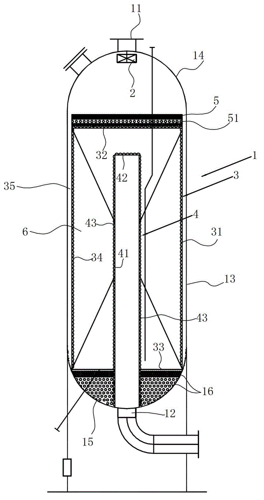
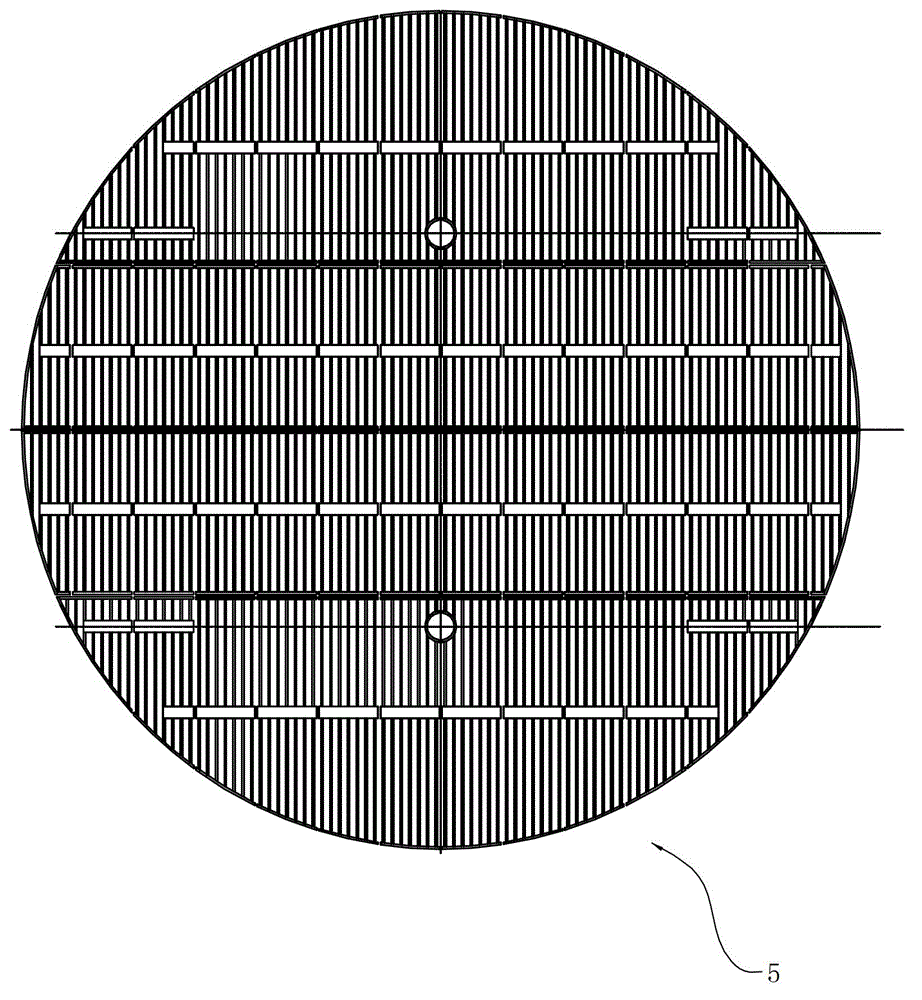
[0022] Such as figure 1 with figure 2 As shown, the axial radial reactor structure for the sulfur-tolerant shift process includes:

[0023] Housing 1, the top of the housing is provided with an air inlet 11, and the bottom of the housing is provided with an air outlet 12; the housing in this embodiment includes a cylindrical main body 13 and upper and lower ends of the cylindrical main body. The length-to-diameter ratio of the cylindrical main body of the sealing head 14 and the lower sealing head 15 is 2. The length-to-diameter ratio of the cylindrical body can be determined according to needs, preferably, it can be 1.0-5.0, and within this range, the weight of the entire reactor can be minimized under the condition of satisfying the process and pressure drop. The lower head 15 is filled with refractory balls, and these refractory balls c...


PUM


Abstract

The invention relates to an axial and radial reactor structure for a sulfur-tolerant conversion process. The axial and radial reactor structure comprises a casing, wherein a gas flow inlet is arranged on the top of the casing, and a gas flow outlet is arranged at the bottom of the casing. The axial and radial reactor structure is characterized in that the reactor structure also comprises a first gas distributor, a second gas distributor and a gas collector, the second gas distributor is used for carrying out secondary redistribution on the gas flow, then, the gas flow enters a catalyst bed layer, a gap is formed between an outer tube body of the second gas distributor and the inner wall of the casing, the gas collector is arranged in the second gas distributor, a gap is formed between a sealing cover of the second gas distributor and a cover net of the first gas distributor, a grating is also arranged above the second gas distributor, and a second heat insulation layer formed by fire-resistant balls is filled between the grating and the cover net. Compared with the prior art, the reactor provided by the invention has the characteristics that the casing wall temperature is low, the pressure drop is low, the equipment diameter is small, the catalyst dead region is small, the reactor space utilization rate is high, the equipment material requirement is low, the equipment weight is light, and the like.

Description

technical field [0001] The invention relates to the field of chemical equipment, in particular to an axial-radial reactor structure for a sulfur-resistant shift process. Background technique [0002] With the increasing development of coal gasification technology and the high oil price, the C1 chemical industry with coal as the source has developed rapidly in recent years, and its scale is increasing day by day. With the launch of a large number of large-scale coal chemical projects such as hydrogen production units supporting oil refining, MTO, and coal-to-ethylene glycol, through actual engineering design, it is found that the proportion of conversion units in the total investment is gradually increasing, almost equivalent to low-temperature methanol A wash unit even exceeds its investment. The reason for this phenomenon is that the investment in equipment and pipelines has increased significantly due to the enlargement of the scale. Among them, the converter furnace is ...

Claims


Application Information

Patent Timeline
Patent Type & Authority Patents(China)
IPC IPC(8): B01J8/02
Inventor 张骏驰杨俊岭胡力刘芹陆亚东
Owner SINOPEC NINGBO ENG
Learn More