Walking beam cooler and stepping control method thereof

A control method and step-by-step technology, which is applied in the direction of cooling bed, metal rolling, manufacturing tools, etc., can solve the problems of movable beam lifting lag, increase of steel plate cooling unevenness, steel plate warping and deformation, etc., and achieve the elimination of lifting lag , Improve cooling uniformity, and prevent warping and deformation

Active Publication Date: 2013-05-01
CISDI ENG CO LTD
View PDF6 Cites 0 Cited by
  • Summary
  • Abstract
  • Description
  • Claims
  • Application Information

AI Technical Summary

Problems solved by technology

[0004] 1) The total time for the steel plate to pass through the cooling bed is composed of several stepping cycles and the waiting time for receiving materials, and the waiting time for receiving materials accounts for a large proportion of the total time; when the cooling bed is in the waiting state for receiving materials, the steel plate is only connected to the fixed Beam contact, and in the stepping cycle, the contact time of the steel plate with the fixed beam and the movable beam is equal, therefore, in the whole cooling process, the total time of the steel plate in contact with the fixed beam is longer, resulting in contact fixation on the steel plate The area of ​​the beam cools quickly, while the area contacting the movable beam cools slowly, which increases the non-uniform cooling of the steel plate in the length direction, resulting in increased internal stress and deformation;
[0005] 2) The distance between the fixed beam and the movable beam is L, and the fixed beam and the

Method used


Image

  • Walking beam cooler and stepping control method thereof
  • Walking beam cooler and stepping control method thereof
  • Walking beam cooler and stepping control method thereof

Examples


Example Embodiment

[0035] The specific embodiments of the present invention will be described in detail below with reference to the accompanying drawings.

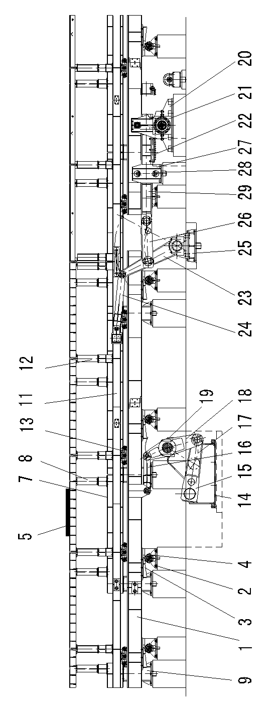
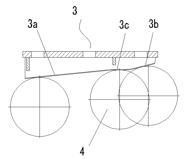
[0036] Such as figure 1 Shown is a schematic structural diagram of an embodiment of the step-by-step cooling bed of the present invention. The stepping cooling bed of this embodiment includes a fixed beam, a movable beam, a lateral shift device, and a lifting device. The lifting device includes a lifting guide mechanism. The lifting guide mechanism includes a lifting seat 2 for supporting the movable beam and a fixed installation on the movable beam. The wedge-shaped lifting lead surface on top and matched with the lifting seat 2. The wedge-shaped lifting lead surface includes a lifting slope 3a, a lifting slope 3b, and a lifting slope located between the two lifting slopes 3a, 3b. In the mid-level horizontal plane 3c, the distance between the top surface of the movable beam and the mid-level horizontal plane 3c is equal to the distance from th...


PUM


Abstract

The invention discloses a walking beam cooler control method, which comprises three stations, i.e. a high station, a middle station and a low station. The starting station of a cooler control cycle is the middle station. The cooler control cycle comprises the following steps of: from the middle station to the high station: starting a lifting device to vertically lift a movable beam to the high station and lift a workpiece to the high station; stepping forwards; and starting a transverse moving device to drive the movable beam to move forwards for one step; from the high station to the low station: starting the lifting device to drive the movable beam to be vertically lowered down to the low station from the high station, and when the top surface of the movable beam and the top surface of a fixed beam are at equal height, placing the workpiece on the fixed beam; stepping backwards; and starting the transverse moving device to drive the movable beam to move backwards for one step; and from the low station to the middle station: starting the lifting device to vertically lift the movable beam to the middle station from the low station to support the workpiece jointly with the fixed beam till the next control period. The invention additionally discloses a walking beam cooler. The cooling uniformity of steel plates can be improved, the buckling deformation is reduced and the situation of lifting delay is eliminated.

Description

technical field [0001] The invention belongs to the technical field of cooling beds, in particular to a step-type cooling bed control method and a step-type cooling bed suitable for the method. Background technique [0002] The medium-thick plate walking cooling bed is composed of a movable beam, a fixed beam, a traverse device and a lifting device. stay on top. The active beam of the existing step-by-step cooling bed has two lifting control positions - high position and low position (relative to the fixed beam). Support), the step control method is: start the lifting device, the movable beam starts to lift from the low position, and after running for a period of time, lift the steel plate from the fixed beam and continue to lift to the high position; then start the traverse device, and the movable beam lifts the steel plate at the high position Move one step forward; start the lifting device again, the movable beam supports the steel plate and descend from the high positi...

Claims


Application Information

Patent Timeline
IPC IPC(8): B21B43/00
Inventor 王勇蒋周强
Owner CISDI ENG CO LTD
Why Eureka
Try Eureka