Eureka AIR delivers breakthrough ideas for toughest innovation challenges, trusted by R&D personnel around the world.

High-concentration straw methane fermentation equipment

A biogas fermentation and high-concentration technology, applied in the energy field, can solve the problems of low material concentration, low input-output ratio, and low utilization rate of raw materials, so as to increase the concentration of fermentation materials, prevent straw from floating and encrusting, and increase volumetric gas production rate effect

Active Publication Date: 2013-05-01
BIOGAS SCI RES INST MIN OF AGRI
View PDF6 Cites 5 Cited by
  • Summary
  • Abstract
  • Description
  • Claims
  • Application Information

AI Technical Summary

Problems solved by technology

[0003] The purpose of the present invention is to overcome the defects of low material concentration and low raw material utilization rate in the prior art straw biogas continuous fermentation device, relying on mechanical equipment for output, large investment in equipment, high energy consumption, and low efficiency of anaerobic digestion and gas production, and provide a A high-concentration straw biogas fermentation device that can directly digest large particles of straw, has low energy consumption, smooth feeding and discharging, and low input-output ratio

Method used


Image

  • High-concentration straw methane fermentation equipment
  • High-concentration straw methane fermentation equipment

Examples


Embodiment 1

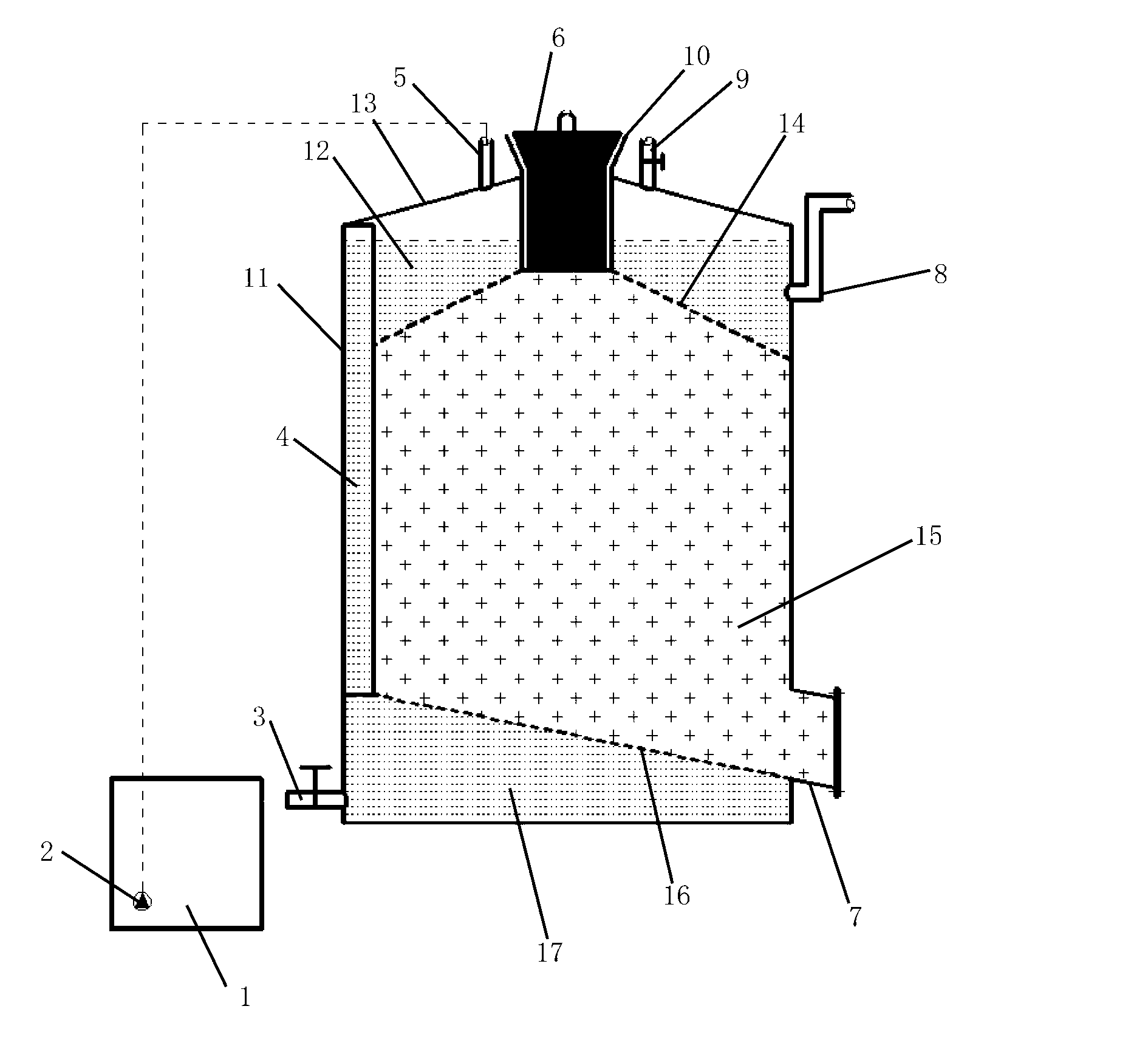
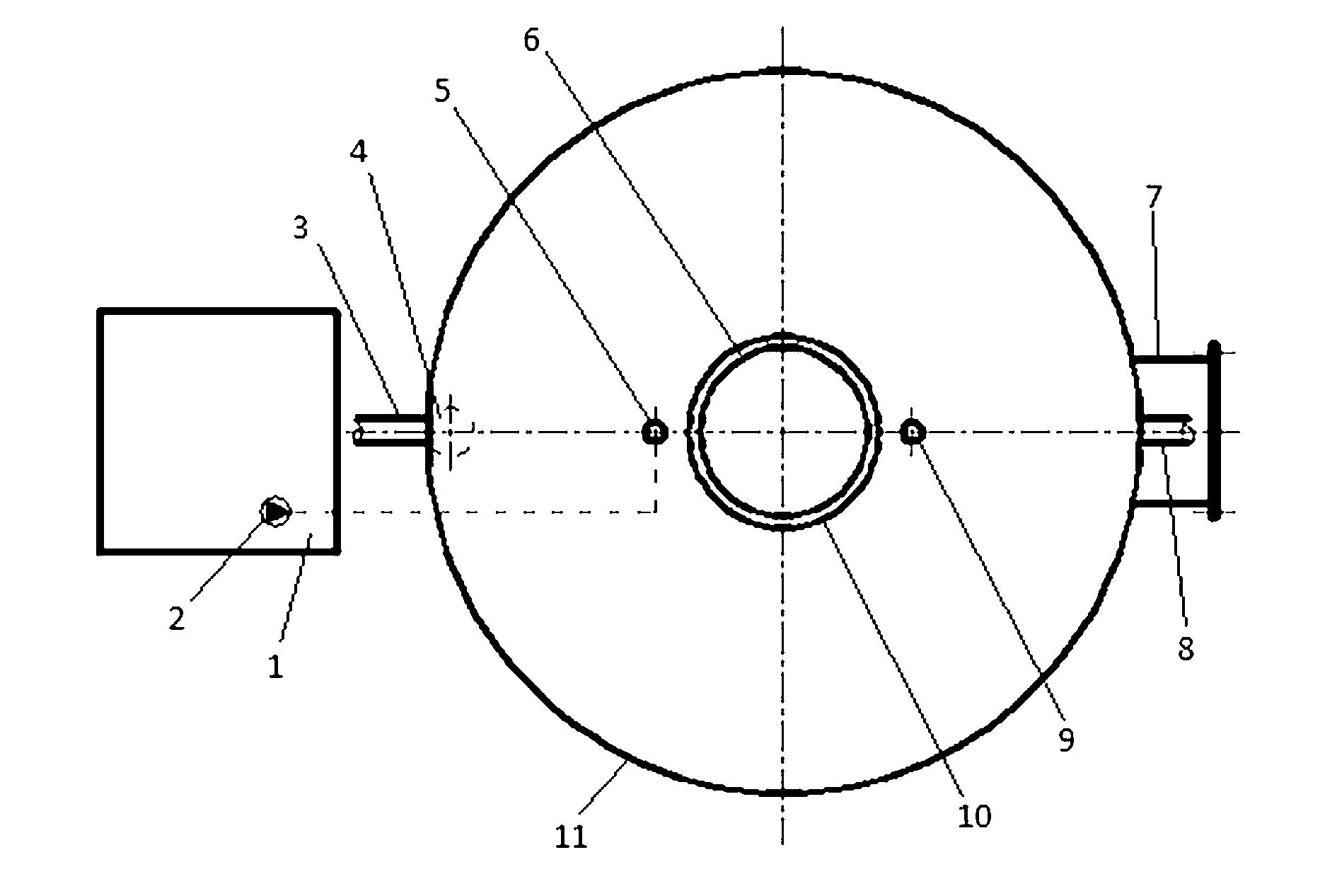
[0020] The high-concentration straw biogas fermentation device in this example is as follows: figure 1 and figure 2 As shown, it is composed of a fermenter 11 and a liquid storage unit 1. The fermenter 11 is a vertical tank body. The top of the tank body is provided with a feed pipe 10 and a biogas nozzle 9 with a valve. The slag mouth 7 is characterized in that a gravity pusher 6 is installed in the feed pipe 10, and the feed pipe 10 is closed by the gravity pusher 6; the top of the tank body is provided with a return nozzle 5, and the return nozzle 5 passes through the circulation The pump 2 is connected with the liquid storage unit 1; the upper part of the tank is provided with an overflow pipe 8, the low point of the overflow pipe 8 is higher than the outlet of the feed pipe 10, and the high point is lower than the inlet of the biogas nozzle 9; the upper part of the tank is installed There is a round table-shaped slag retaining ring plate 14, the upper end of the slag re...

Embodiment 2

[0033] The high-concentration straw biogas fermentation device of this example is the same as the first embodiment except that no connecting pipe is installed.

Embodiment 3

[0035] The high-concentration straw biogas fermentation device of this example is the same as the first embodiment except that the liquid storage unit 1 is a liquid storage tank, and the drain pipe 3 and the overflow pipe 8 are connected to the liquid storage tank.


PUM


Abstract

The invention belongs to the field of energy sources and relates to high-concentration straw methane fermentation equipment which comprises a fermentation tank (11) and a liquid storage unit (1), wherein a feed pipe (10) and a methane pipe orifice (9) are arranged at the top of a tank body; a slag discharge port (7) is formed at the bottom of the tank body; the feed pipe (10) is internally provided with a gravity material pusher (6); a circular-table-shaped slag blocking ring plate (14) is mounted at the upper part in the tank body; the upper end of the slag blocking ring plate (14) is connected with an outlet of the feed pipe (10) and the lower end thereof is connected with an internal wall of the tank body; sieve pores are formed in the ring plate; a liquid-slag separation plate (16) is mounted at the lower part in the tank body; sieve pores are formed in the liquid-slag separation plate (16); the periphery of the liquid-slag separation plate (16) is connected with the internal wall of the tank body; a liquid discharge pipe (3) is arranged at the bottom of the fermentation tank (11); and an outlet of the liquid discharge pipe (3) corresponds to or is connected with the liquid storage unit (1). The high-concentration straw methane fermentation equipment can directly consume bulky-grain straw, is low in energy consumption, smooth in feeding and discharging, and low in input-output ratio.

Description

technical field [0001] The invention belongs to the field of energy, and in particular relates to a high-concentration straw biogas fermentation device. Background technique [0002] Crop stalks come from a wide range of sources, and the amount of resources is large. A large amount of stalks cannot be effectively treated, which brings a series of environmental problems. Straw biogas utilization can effectively solve this problem, and at the same time produce high-quality bioenergybiogas, which has become one of the important means of straw resource utilization. The raw materials of existing straw continuous fermentation devices generally need to be pretreated such as crushing, because of their poor fluidity, mechanical stirring is usually required to achieve mass and heat transfer. The specific gravity of the straw is light, and it is easy to float up to form a hard shell after entering the fermentation device, which hinders the accumulation of biogas generated in the pond...

Claims


Application Information

Patent Timeline
IPC IPC(8): C12M1/107
CPCC12M23/34C12M45/04C12M21/04Y02E50/30
Inventor 罗涛梅自力施国中徐彦胜
Owner BIOGAS SCI RES INST MIN OF AGRI
Why Eureka
Eureka Blog
Learn More