Thermosyphon waste heat power generating system

A waste heat power generation and thermosiphon technology, which is applied to machines/engines, steam engines, mechanical equipment, etc., can solve the problems of large floor space, high investment and operating costs, and achieve small floor space, high-efficiency operation, and low failure rate. Effect

Inactive Publication Date: 2015-03-11
BEIJING CENTURY BENEFITS
View PDF10 Cites 0 Cited by
  • Summary
  • Abstract
  • Description
  • Claims
  • Application Information

AI Technical Summary

Problems solved by technology

[0007] The purpose of the present invention is to solve the problems existing in the thermal system of the existing waste heat power station. The system breaks the pattern of copying the thermal system design of the small thermal power station in the existing waste heat power station, and proposes a new type of thermal system according to the unique characteristics of the waste heat power station. The system proposed by the invention adopts the high-level vertical layout mode of the integrated condensing cooling and deaeration device, and strives to solve the problems of large floor area, high investment and operating costs of the existing system

Method used


Image

  • Thermosyphon waste heat power generating system
  • Thermosyphon waste heat power generating system
  • Thermosyphon waste heat power generating system

Examples


Embodiment Construction

[0019] The content of the present invention will be described in further detail below in conjunction with the accompanying drawings and specific embodiments.

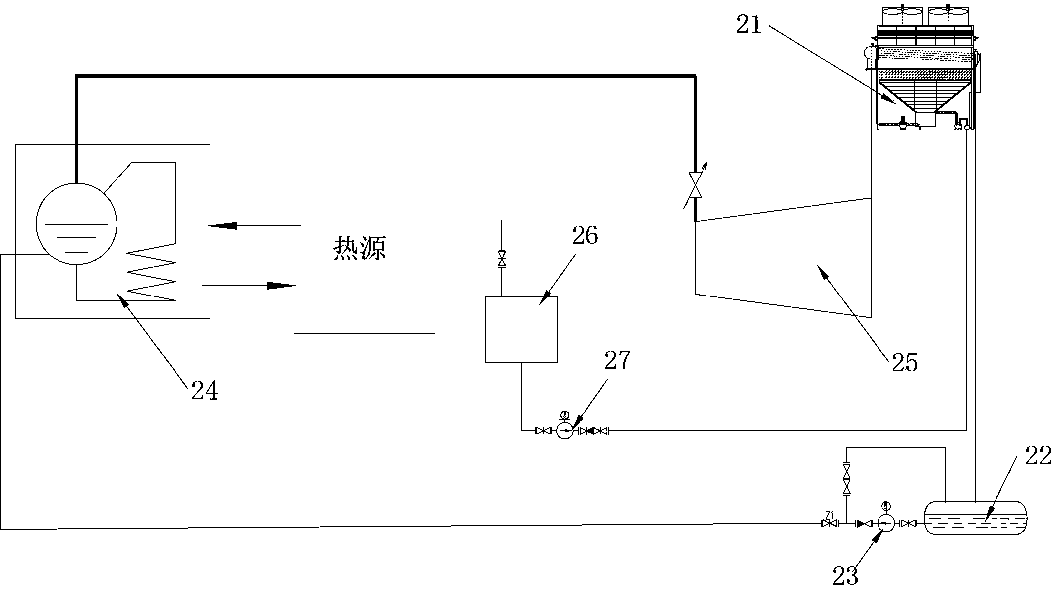
[0020] as read figure 2 As shown: the thermosiphon waste heat power generation system, including an integrated condensing cooling deaeration device 21, the outlet end of the integrated condensing cooling deaeration device 21 is connected to the condensed water tank 22, the feed water pump 23, the waste heat boiler 24, the steam turbine 25, and the steam turbine 25 row The steam end is connected to the inlet end of the integrated condensing cooling and deaeration device 21, and the position of the integrated condensing cooling and deaeration device 21 is arranged vertically at a high position. The vertical arrangement at the high position is: relative to the steam turbine 25 and the condensed water tank 22 The integrated condensing cooling deaeration device 21 is located at a high position above the steam turbine 25 and...


PUM


Abstract

The invention discloses a thermosyphon waste heat power generating system which comprises an integrated condensing, cooling and deaerating device. One end of the integrated condensing, cooling and deaerating device is sequentially connected with a condensing water tank, a water feed pump, a waste heat boiler and a turbine. The other end of the turbine is connected with the integrated condensing, cooling and deaerating device which is vertically arranged in a high position. The integrated condensing, cooling and deaerating device is located above the turbine and the condensing water tank and height of the device meets the condition that the pressure of a condensing water pipe to the condensing water tank is positive. The integrated condensing, cooling and deaerating device exchanges heat directly by phase change to replace the original sensible heat indirect heat exchange, and the cooling water quantity is greatly reduced, so that the device can be probably vertically arranged. Meanwhile, the back pressure of the turbine is effectively reduced. Therefore, the system fits the characteristic of a waste heat power station and overcomes the deficiencies of current systems. The purposes of simple and capable system, small occupied area, investment saving, high efficiency, less auxiliary power, high reliability, low failure rate and the like can be realized.

Description

technical field [0001] The invention belongs to the thermodynamic system of waste heat power station. Background technique [0002] figure 1 It is a schematic diagram of the thermal system of the existing conventional waste heat power station. The main equipment includes condenser, condensate pump, jet extractor, jet pump, jet tank, jet drainage pump, deaerator, feed water pump, make-up water pump, water storage tank, circulating water pump, cooling tower, waste heat boiler, heat source, steam turbine Wait. The working principle is: the feed water absorbs heat in the waste heat boiler to generate steam and enter the steam turbine to do work. The exhaust steam is cooled by circulating water into condensed water and discharged into the hot well, and then lifted to the deaerator by the condensed water pump; after absorbing heat, the circulating water enters the cooling tower to release heat for cooling. The condensed water is sent to the waste heat boiler by the feed water ...

Claims


Application Information

Patent Timeline
Patent Type & Authority Patents(China)
IPC IPC(8): F01K11/02F01D15/10
Inventor 陈恩鉴徐晓丽
Owner BEIJING CENTURY BENEFITS
Why Eureka
Try Eureka