Optical imaging method integrating three-dimensional mapping and broad width imaging

A technology of three-dimensional surveying and mapping and optical imaging, which is applied in the field of optical imaging, can solve the problems of insufficient three-dimensional surveying and mapping capabilities, affecting the use efficiency of space-based equipment, and insufficient ability to identify conventional targets on the ground, so as to avoid the decline of three-dimensional surveying and mapping accuracy indicators and achieve good results. The effect of engineering realizability and improvement measures is simple and easy

Inactive Publication Date: 2013-05-01
CHINA ACADEMY OF SPACE TECHNOLOGY
View PDF3 Cites 18 Cited by
  • Summary
  • Abstract
  • Description
  • Claims
  • Application Information

AI Technical Summary

Problems solved by technology

Ocean surveillance satellites are mainly to achieve large-scale sea area searches. According to the characteristics of wide distribution of ocean areas and large target scales, it is determined that they must give priority to ensuring wide coverage, and the imaging resolution requirements are relatively low. For example, ocean surveillance satellites are directly applied to land observation. , its resolution is slightly insufficient to identify conventional targets on the ground, and its positioning accuracy is low, so it cannot provide accurate geographic information; in contrast, the main function of land surveying and mapping satellites is to provide accurate and detailed basic geographic information on land. The imaging width is narrow, which cannot meet the needs of wide-range surveillance in large-scale sea areas, and the advantages of its three-dimensional mapping capabilities are of little significance in ocean target surveillance
[0004] The difference in application requirements and load capacity determines that the three-dimensional mapping satellites and ocean surveillance satellites using the traditional system cannot be shared, which greatly reduces the appropriate imaging area and working time of each in orbit, and the limited imaging resources are not fully utilized. Effectiveness of use of space-based equipment

Method used


Image

  • Optical imaging method integrating three-dimensional mapping and broad width imaging
  • Optical imaging method integrating three-dimensional mapping and broad width imaging
  • Optical imaging method integrating three-dimensional mapping and broad width imaging

Examples


Embodiment

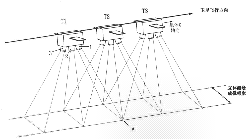
[0039] The main index parameters of the satellite are set as follows: the satellite orbit adopts sun-synchronous homing orbit, the orbital height is 500km, three TDICCD line array cameras form a front-view, front-view and rear-view layout at a intersection angle of 21°, and the imaging width of a single camera is 100km. The formed three-dimensional mapping width is also 100km, and the distance between the ground coverage strips of the front-view and front-view cameras is S=500×tan 21° = 192 km. The baseline length is twice the interval S.

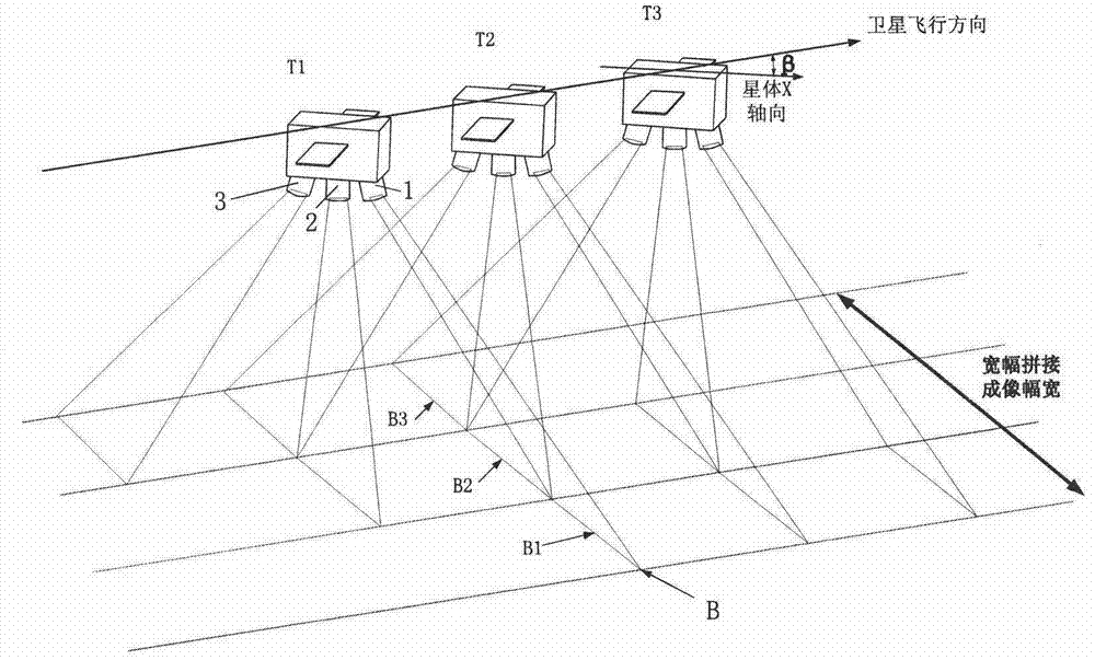
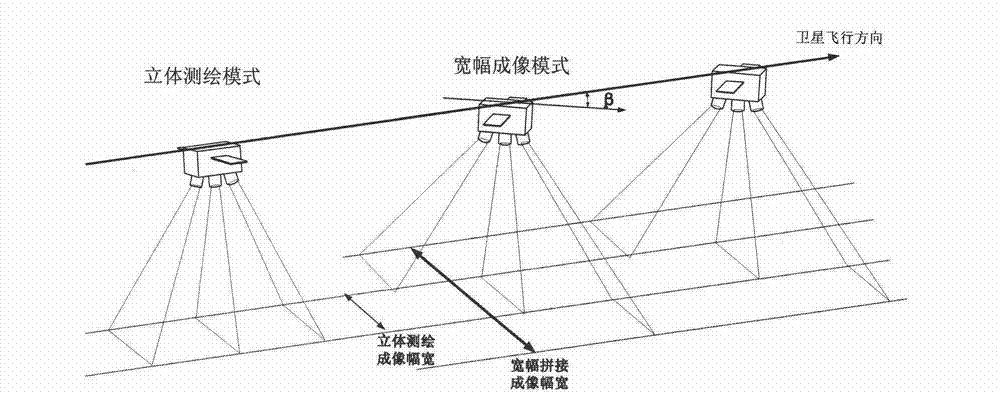
[0040] When performing wide-format stitching imaging, the whole star needs to yaw at a certain initial angle β, and switch the imaging detector. When setting wide stitching, the coverage width W achieved by a single line scan camera is also 100km, and the value of β is β=arcsin(W / S)=arcsin(100 / 192)=31.4°, such as Figure 6 shown. At this time, the strips formed by the front-view camera and the front-view camera on the ground push-broom...


PUM


Abstract

The invention discloses an optical imaging method integrating three-dimensional mapping and broad width imaging. According to the invention, two or three line-scan digital cameras are installed on a satellite within certain interaction angles; each line-scan digital camera is provided with a first imaging detector for three-dimensional mapping and a second imaging detector for broad width imaging, and the conversion between the two imaging detectors are realized by cutting in a reflecting mirror; when the three-dimensional mapping is performed, the satellite flies in a normal attitude, and the imaging detection is realized through the first imaging detector of each line-scan digital camera; and when the broad width monitoring is performed, the satellite flies by yawing a certain angles and converts light paths by cutting in the reflecting mirror, adjacent air strips on the ground are sequentially imaged through the second imaging detector of each line-scan digital camera, and equivalently a wide air strip on the ground is imaged in a segmentation spliced manner, and accordingly the imaging width is remarkably increased. The optical imaging method integrating three-dimensional mapping and broad width imaging realizes multiplexing of the single-satellite function and improves the utilization ratio of on-orbit resources.

Description

technical field [0001] The invention belongs to the technical field of optical remote sensing imaging, and relates to an optical imaging method based on the principle of three-line array or two-line array surveying and mapping, which can simultaneously meet the requirements of three-dimensional surveying and mapping and wide-width imaging by using one satellite. Background technique [0002] The modern combat system's intelligence support requirements for space-based battlefield reconnaissance and surveillance tend to be diversified. According to the different objects of remote sensing detection and intelligence collection purposes, my country has developed and launched a variety of special detection payloads and special satellites, which are improving the space-based remote sensing detection. At the same time, there are also problems such as the system is too complex, the satellite functions and applications are single, and the on-orbit imaging resources are not fully utilize...

Claims


Application Information

Patent Timeline
Patent Type & Authority Applications(China)
IPC IPC(8): G01C11/00G03B35/20G03B37/02
Inventor 王世涛宋鹏飞王虎妹石俊田坤黉
Owner CHINA ACADEMY OF SPACE TECHNOLOGY
Why Eureka
Try Eureka