Optical fiber sensing device based on composite material

An optical fiber sensing and composite material technology, which is applied in the use of optical devices, measuring devices, and the measurement of force by measuring the change of optical properties of materials when they are stressed, can solve the problem of restricting the popularization and use of optical fiber sensors and affecting the use of sensing devices. and accuracy, fracture sensor and other issues, to achieve the effect of excellent environmental adaptability, flexible use and high sensitivity

Inactive Publication Date: 2013-05-01
XIAN JINHE OPTICAL TECH
View PDF1 Cites 4 Cited by
  • Summary
  • Abstract
  • Description
  • Claims
  • Application Information

AI Technical Summary

Problems solved by technology

However, when monitoring large deformations such as landslides, the general column material cannot meet the requirements. When the column material is made of metal, although it has a certain rigidity, the deformation is small. After a certain deformation, the column material There will be fractures and the sensor will fail; when choo

Method used


Image

  • Optical fiber sensing device based on composite material
  • Optical fiber sensing device based on composite material
  • Optical fiber sensing device based on composite material

Examples


Embodiment 1

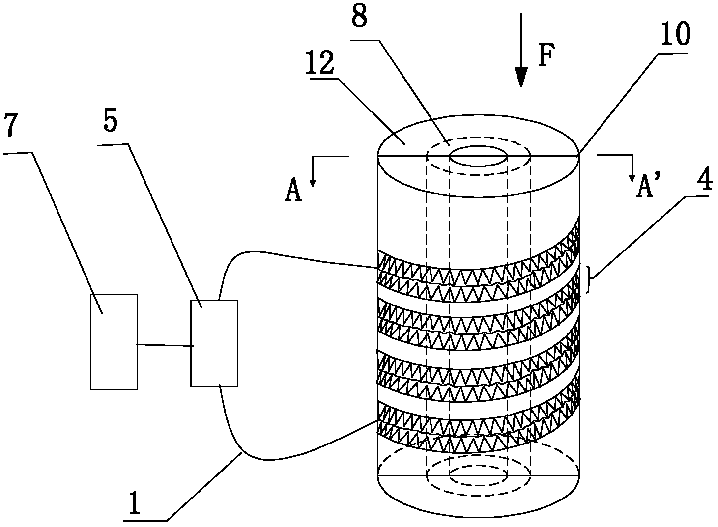
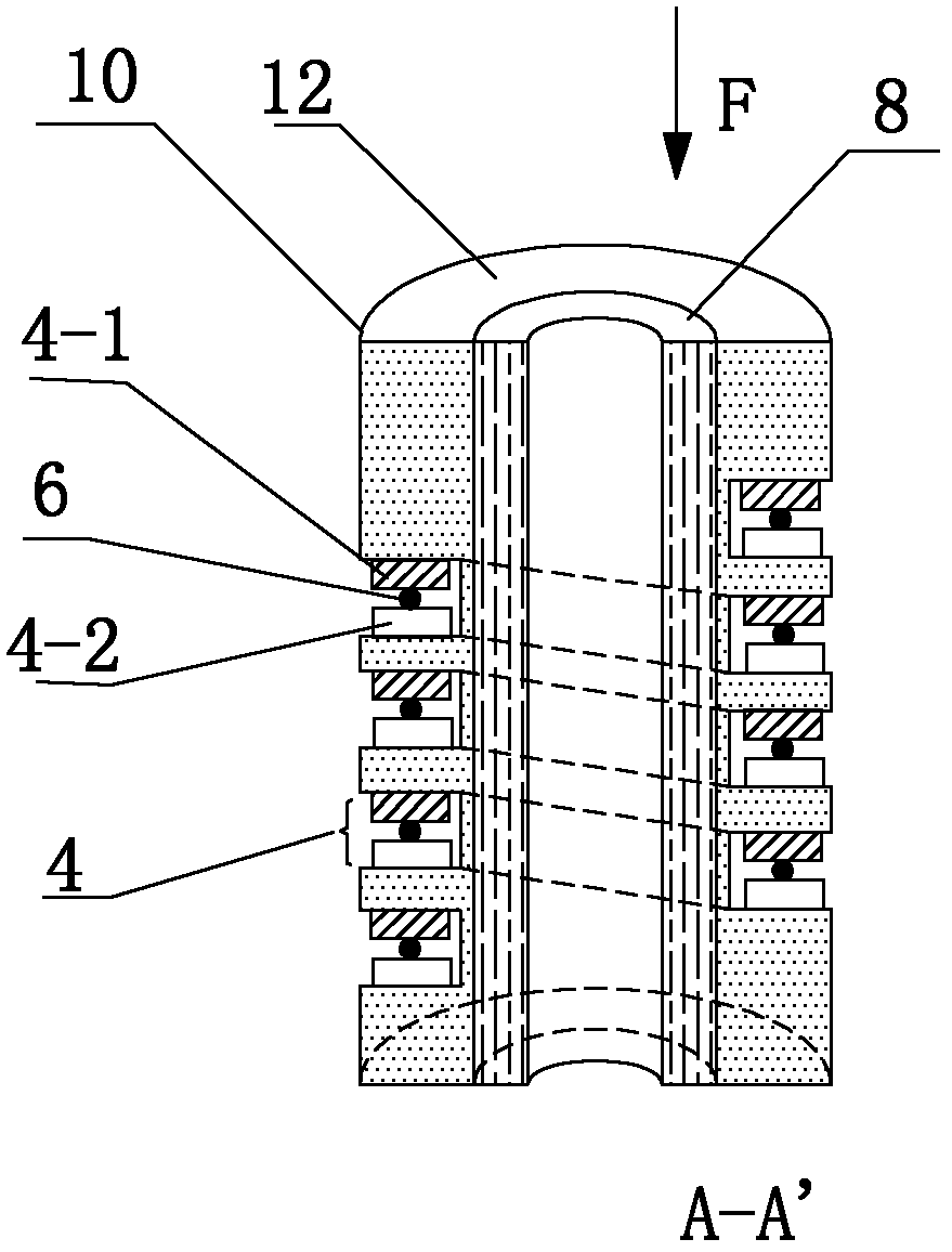
[0032] Such as figure 1 , figure 2 As shown, the present invention includes grooves 4 distributed on the cylinder 10, the opposite sides of the grooves 4 respectively have A-side deformation teeth 4-1 and B-side deformation teeth 4-2 corresponding to each other, and in the grooves There is a signal optical fiber 6 sandwiched between the deformed teeth on opposite sides of 4, the signal optical fiber 6 is connected to the test unit 5 through the extension optical fiber 1, and the processing unit 7 is connected behind the test unit 5, especially the cylinder 10 is composed of different materials , that is, it is composed of the reinforcement layer 8 and the outermost layer 12 .

[0033] Preferably, the reinforcing layer 8 is made of polymer material and reinforced fiber composite material, so that the column 10 not only has a certain rigidity, but also has a large deformation capacity; when the column 10 is deformed under stress, the groove The width of 4 changes, so that the...

Embodiment 2

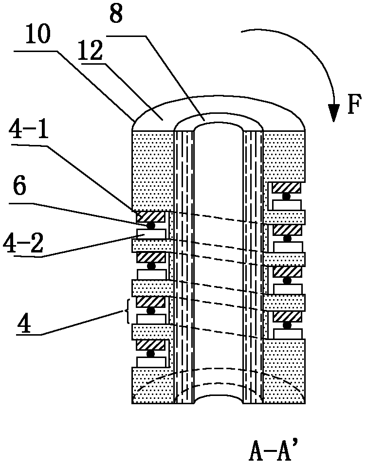
[0039] Such as image 3 As shown, in this embodiment, the difference from Embodiment 1 is that the applied stress F acts on the upper end or the lower end of the cylinder 10, so that the cylinder 10 presents an overall bending. In this embodiment, the structures, connections and working principles of other parts are the same as those in Embodiment 1.

Embodiment 3

[0041] Such as Figure 4 As shown, in this embodiment, the difference from Embodiment 1 is that the cylinder 10 is composed of three layers of materials.

[0042] Preferably, the base material of the reinforcing layer 8 is hot-melt adhesive, and its reinforcing fibers are steel wires, so as to ensure the rigidity and deformability of the column 10, the cost can be reduced, and it is easy to popularize and implement.

[0043] Preferably, the outermost layer of the cylinder 10 is made of rigid polyvinyl chloride, and the grooves are also distributed on this layer of material.

[0044] Preferably, the material of the innermost layer of the cylinder 10 is polyethylene.

[0045] In this embodiment, the structures, connections and working principles of other parts are the same as those in Embodiment 1.


PUM


Abstract

The invention discloses an optical fiber sensing device based on composite material. The device comprises a column body and a groove formed in the column body; deformed teeth which are staggered and corresponding to one other are respectively formed on opposite two surfaces of the groove; and signal fiber is clamped between the deformed teeth arranged two opposite surfaces of the groove; the signal fiber is connected with a test unit; the column body is made of at least 2-layered composite materials, and different materials are distributed along the radial direction of the column body layer by layer. The optical fiber sensing device provided by the invention greatly reduces the weight of the column body on the basis of ensuring the rigidity, and has larger deformation capability, so that an optical fiber stress monitoring device provided by the invention has the characteristics of long service life, high precision and wide usage.

Description

technical field [0001] The invention belongs to the technical field of optical fiber sensing devices, in particular to an optical fiber sensing device based on composite materials. Background technique [0002] Due to the need for health monitoring of landslides, debris flows, earthquakes, and large artificial buildings, the monitoring of stress and strain parameters is one of the most important parameters that technicians care about. Defects in other aspects lead to a relatively narrow range of applications. With the in-depth understanding of optical fiber and the development of optical fiber technology, more and more scholars tend to use optical fiber technology solutions for point and distributed monitoring of stress. Chinese patent application number 201020516566.7 "A Cylinder Stress Sensing Device" In the patent literature, a cylindrical optical fiber micro-bending principle sensing device is proposed. Through the prefabricated micro-bending structure, the sensing opti...

Claims


Application Information

Patent Timeline
IPC IPC(8): G01L1/24G01B11/16
Inventor 杜兵
Owner XIAN JINHE OPTICAL TECH
Why Eureka
Try Eureka