
Automatic sampling system for radioactive gas-carrying discharge substances

A technology for automatic sampling and effluent, applied in the direction of sampling devices, etc., it can solve the problem that continuous sampling or regular sampling monitoring is infeasible, cannot truly and objectively reflect the emission source items of chimney airborne substances, and cannot reflect the working conditions of airborne substances. and other issues to achieve a practical effect

Inactive Publication Date: 2013-05-01
INST OF NUCLEAR PHYSICS & CHEM CHINA ACADEMY OF
View PDF6 Cites 7 Cited by
  • Summary
  • Abstract
  • Description
  • Claims
  • Application Information

AI Technical Summary

Problems solved by technology

[0002] At present, in view of the situation that multiple radioactive sites are built on the same site, according to the requirement of "unified effluent monitoring" in the four unifications proposed by the Ministry of Environmental Protection, the discharge of airborne materials is usually carried out by multiple nuclear facilities (devices), The waste gas generated in radioactive places such as production lines is discharged to the environment through a single chimney. Due to the differences in the radioactivity concentration and total amount of airborne substances, the working mode of the ventilation and exhaust system, and the size of the exhaust air in different radioactive places, the effluent monitoring is based on the current general Neither the continuous sampling nor the regular sampling monitoring mode is feasible, neither can reflect the airborne material discharge conditions of each radioactive site, and the monitoring results cannot truly and objectively reflect the chimney’s impact on the airborne material discharge source items of each radioactive site.

Method used


Image

  • Automatic sampling system for radioactive gas-carrying discharge substances

Examples


Embodiment 1

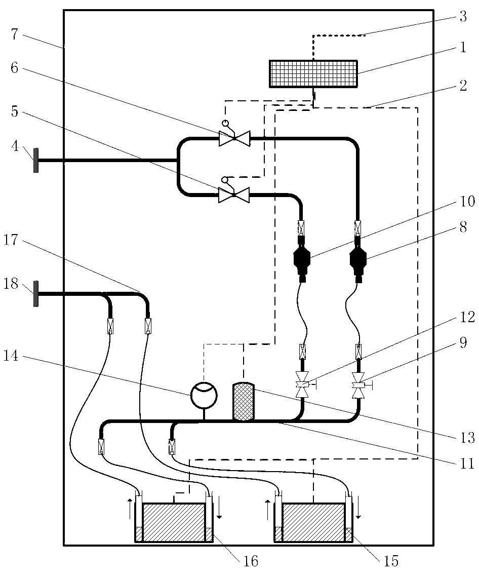
[0018] figure 1 It is a schematic diagram of the structure of the present invention. exist figure 1 Among them, the radioactive airborne effluent automatic sampling system of the present invention comprises an automatic control unit 1, a first solenoid valve 6, a second solenoid valve 5, a first aerosol and iodine sampling head 8, a second Aerosol and iodine sampling head 10, mass flow meter 13, pressure gauge 14, pump I15 and pump II16 also include the inlet pipe joint 4 and exhaust pipe joint 18 that are arranged on the outside of sampling cabinet 7; Its connection relationship is, is arranged on The inlet pipe joint 4 outside the sampling cabinet 7 is connected with the first solenoid valve 6 and the second solenoid valve 5 respectively by the gas pipe; the first solenoid valve 6 is connected with the first aerosol and an end of the iodine sampling head 8 by the gas pipe, The other end of sol and iodine sampling head 8 is connected with an end of first flow regulating val...


PUM


Abstract

The invention provides an automatic sampling system for radioactive gas-carrying discharge substances, and belongs to the technical fields of radiation protection and environment protection. An intake tube joint in the sampling system is connected with a solenoid valve through a gas tube; the solenoid valve is connected with an aerosol and iodine sampling head through a gas tube; the aerosol and iodine sampling head is connected with a flow regulating valve through a hose; the flow regulating valve is sequentially connected with a mass flowmeter and a pressure gage through a gas tube and is then connected with a gas inlet of a pump through a hose; the gas inlet of the pump is connected with an exhaust tube joint through an exhaust tube; the signal input end of an automatic control unit is in external connection with a chimney flow monitoring PLC (programmable logic controller); and the signal output end of the automatic control unit is sequentially connected with the solenoid valve, the mass flowmeter, the pressure gage and the pump. The automatic sampling system can not only improve the representativeness of large differences of discharge source items of the gas-carrying substances and discharge substance samples in scattered discharge, but also reduces labor intensity of staff for monitoring and sampling the discharge substances and improves the working efficiency, and has the characteristics of intelligent regulation, unattended operation and high practicability.

Description

technical field [0001] The invention belongs to the technical field of radiation protection and environmental protection, and in particular relates to an automatic sampling system for radioactive airborne effluents, especially for the sampling of radioactive airborne effluents in multiple nuclear workplaces, work stations or hot rooms when they are discharged through chimneys. Automatic system for dynamic sampling of effluents. It is suitable for sampling of fine dust aerosol and iodine aerosol in airborne effluent emission monitoring. Background technique [0002] At present, in view of the situation that multiple radioactive sites are built on the same site, according to the requirement of "unified effluent monitoring" in the four unifications proposed by the Ministry of Environmental Protection, the discharge of airborne materials is usually carried out by multiple nuclear facilities (devices), The waste gas generated in radioactive places such as production lines is dis...

Claims


Application Information

Patent Timeline
IPC IPC(8): G01N1/24
Inventor 周银行林青川胥全敏郭洪波刘秀华何小波龙素群钟志京王和义李奎
Owner INST OF NUCLEAR PHYSICS & CHEM CHINA ACADEMY OF
Learn More