Coupling device and method for narrow spectral high-power semiconductor laser

A coupling device and semiconductor technology, which is applied in the coupling of semiconductor laser devices, laser devices, and optical waveguides, can solve the problems of inability to realize single-tube semiconductor laser feedback and simultaneous inability to achieve convenient adjustment, high electro-optical conversion efficiency, and stability good sex effect

Inactive Publication Date: 2013-05-01
FOCUSLIGHT TECH
View PDF3 Cites 13 Cited by
  • Summary
  • Abstract
  • Description
  • Claims
  • Application Information

AI Technical Summary

Problems solved by technology

[0004] For a single-tube semiconductor laser or a single-bar laser to achieve a narrow spectral output, only the beam emitted by a single tube or a single bar can be incident on the VBG, and only a single single-tube laser can be fed back to the single channel along the original path of the outgoing light path. In the active

Method used


Image

  • Coupling device and method for narrow spectral high-power semiconductor laser
  • Coupling device and method for narrow spectral high-power semiconductor laser
  • Coupling device and method for narrow spectral high-power semiconductor laser

Examples


Embodiment 1

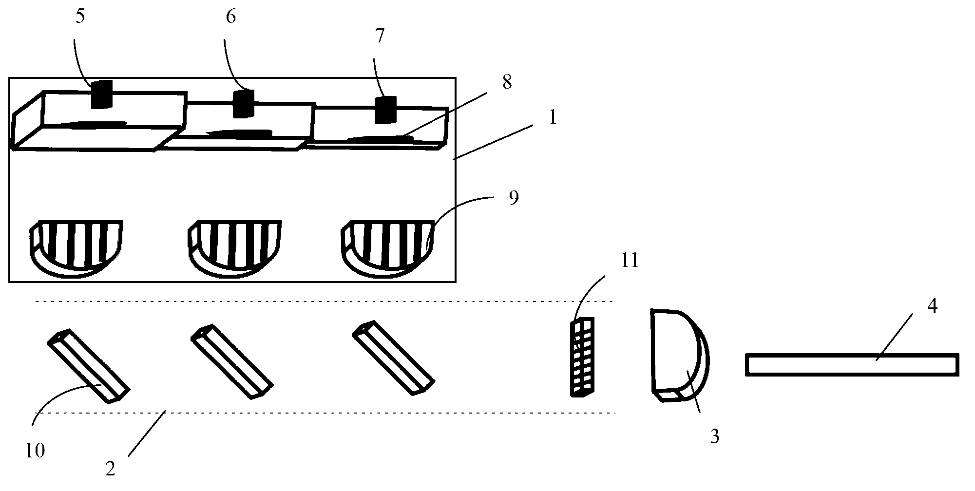
[0025] like figure 1 As shown, wherein, 1 is a semiconductor laser system, including semiconductor lasers 5, 6, 7 and fast axis collimating mirrors 8 and slow axis collimating mirrors 9 installed in front of semiconductor lasers 5, 6, 7; semiconductor lasers 5, 6, 7 is a multi-light-emitting unit laser with a light-emitting wavelength of 808nm, which is a laser with three light-emitting units;

[0026] A fast-axis collimator mirror 8 and a slow-axis collimator mirror 9 are arranged at the light-emitting surface ends of the semiconductor laser 5, semiconductor laser 6, and semiconductor laser 7 respectively; the multi-beam original path feedback system 2 is placed at the light-emitting end of the semiconductor laser system 1, and the multi-beam The original feedback system 2 includes: a reflector 10, a transmissive volume Bragg grating 11 (VBG); Returned along the original path, part of the light directly passes through the transmissive volume Bragg grating 11 , and the transm...

Embodiment 2

[0034] The basic structure of the system is the same as that of Embodiment 1. Among them, the discrete lasers 5, 6, and 7 are single-tube lasers with an emission wavelength of 808nm;

[0035] A fast-axis collimator mirror 8 and a slow-axis collimator mirror 9 are arranged at the light-emitting surface ends of the semiconductor laser 5, semiconductor laser 6, and semiconductor laser 7 respectively; the multi-beam original path feedback system 2 is placed at the light-emitting end of the semiconductor laser system 1, and the multi-beam The original feedback system 2 includes: a reflector 10, a transmissive volume Bragg grating 11 (VBG); Returned along the original path, part of the light directly passes through the transmissive volume Bragg grating 11 , and the transmitted light is coupled into the optical fiber 4 through the focusing lens 3 .

[0036] Another VBG-based external cavity feedback multi-single-tube coupling semiconductor laser of the present invention has a multi-...


PUM


Abstract

The invention relates to a coupling device and method for a narrow spectral high-power semiconductor laser. The device is characterized by comprising a semiconductor laser system, a light beam backtrack feedback system, a focusing lens and output optical fiber; the semiconductor layer system consists of a plurality of semiconductor lasers which are provided with fast axis collimation lenses or a plurality of semiconductor lasers which are provided with fast axis and slow axis collimation lenses; the light beam backtrack feedback system comprises a reflective lens group which is arranged in sequence along the laser emission direction and a transmission-type volume bragg grating (VBG) of which position is adjustable; and the focusing lenses is arranged on the output end surface of the transmission-type volume bragg grating so as to focus the light transmitted and output by the transmission-type volume bragg grating, the optical fiber is arranged at the output end of the focusing lens so as to perform optical fiber coupling on the light which is output by the focusing lens. The device and the method provided by the invention have the advantage that the power is expandable.

Description

technical field [0001] The invention belongs to the field of high-power semiconductor lasers, and relates to a shaping device and method for high-power semiconductor lasers, in particular to a coupling method for multiple semiconductor lasers. Background technique [0002] At present, semiconductor lasers and their fiber coupling systems are developing towards high output power, and are being used more and more widely in industrial, medical, military and other fields. The coupling of multiple semiconductor lasers is a kind of integration of multiple semiconductor lasers, and after the optical system combines the beams, the output power can be further improved. Although the output power of multiple semiconductor lasers is improved after coupling, the output bandwidth is wider. In the application of pumping fiber lasers, too wide output bandwidth will greatly reduce the pumping efficiency. [0003] The usual method for single tube and single bar is to place a volume Bragg gr...

Claims


Application Information

Patent Timeline
IPC IPC(8): H01S5/40H01S5/14G02B27/10G02B6/32
Inventor 蔡万绍刘兴胜
Owner FOCUSLIGHT TECH
Why Eureka
Try Eureka