Combined cycle power generation plant utilzing solar heat

A combined cycle, solar thermal technology, applied in solar thermal power generation, solar thermal installations, solar thermal energy, etc., can solve the problems of reduced power generation output and thermal efficiency, and reduced air intake of compressors, so as to maintain power generation output and restrain thermal efficiency. reduced effect

Active Publication Date: 2013-05-01
MITSUBISHI POWER LTD
View PDF8 Cites 7 Cited by
  • Summary
  • Abstract
  • Description
  • Claims
  • Application Information

AI Technical Summary

Problems solved by technology

It is known that when the gas turbine power plant and the combined cycle power plant are operated during a period when the atmospheric temperature rises, such as in summer, the amount of air intake by the compressor is relatively reduced compared with the case of operating during a period when the atmospheric temperature is low , power generation output and thermal efficiency decrease

Method used


Image

  • Combined cycle power generation plant utilzing solar heat
  • Combined cycle power generation plant utilzing solar heat
  • Combined cycle power generation plant utilzing solar heat

Examples


no. 1 approach

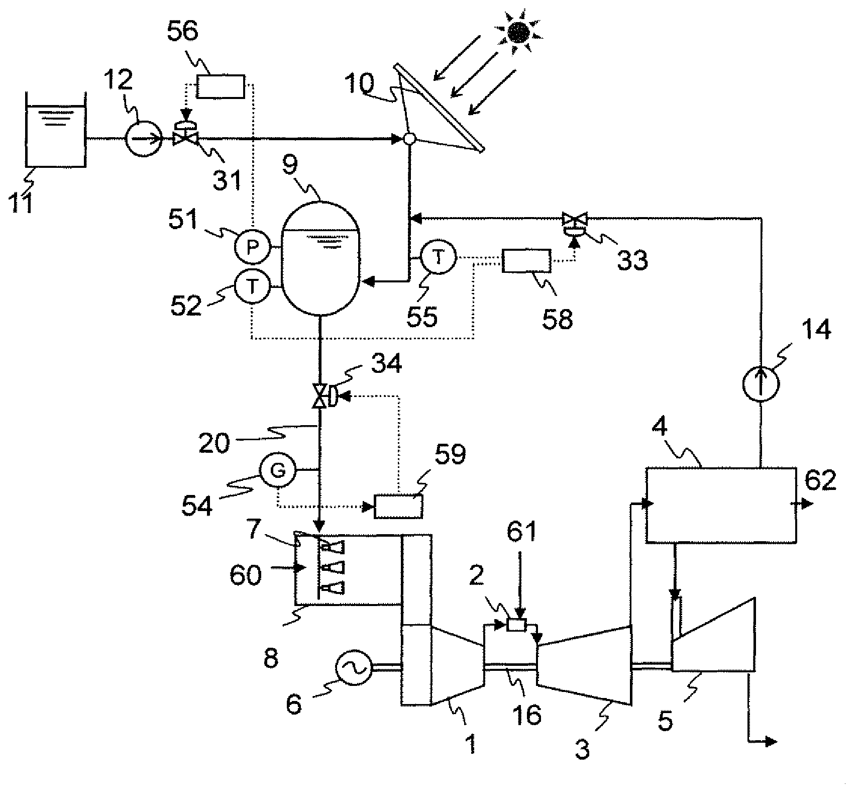
[0024] Hereinafter, a first embodiment of the solar heat utilization combined cycle power plant of the present invention will be described using the drawings. figure 1 It is a system configuration diagram showing the first embodiment of the solar heat utilization combined cycle power plant of the present invention.

[0025] figure 1 It shows the system flow of a combined cycle power plant having a heat collector, a heat accumulator, a spraying device, a gas turbine, an exhaust heat recovery boiler, and a steam turbine, which will be described later.

[0026] exist figure 1 Among them, the combined cycle power plant includes a compressor 1 , a combustor 2 , a gas turbine 3 , an exhaust heat recovery boiler 4 , a steam turbine 5 , and a generator 6 . The compressor 1 takes in air from the intake duct 8 , pressurizes it, and supplies it to the combustor 2 as combustion air 60 . The combustor 2 mixes and burns the gas turbine fuel 61 and the combustion air 60 to generate high-t...

no. 2 approach

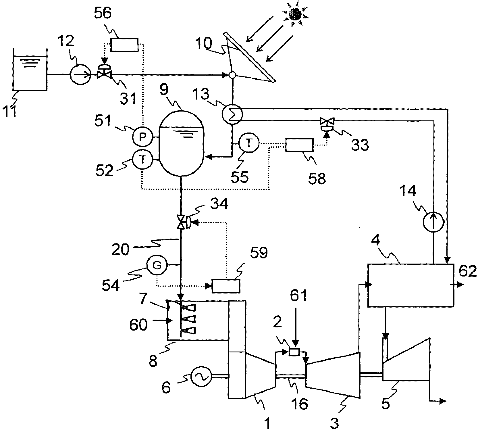
[0048] Hereinafter, a second embodiment of the solar heat utilization combined cycle power plant of the present invention will be described with reference to the drawings. figure 2 It is a system configuration diagram showing the second embodiment of the solar heat utilization combined cycle power plant of the present invention. exist figure 2 in, with figure 1 The same symbols as shown are the same parts, and therefore detailed description thereof will be omitted.

[0049] figure 2 Represents the system flow of a combined cycle power plant with collectors, heat storage, spraying plant, gas turbine, heat recovery boiler, steam turbine. The second embodiment of the solar heat utilization combined cycle power plant of the present invention is composed of the same combined cycle power plant as that of the first embodiment, but differs in the following configurations.

[0050] In the first embodiment of the solar heat utilization combined cycle power plant of the present in...

no. 3 approach

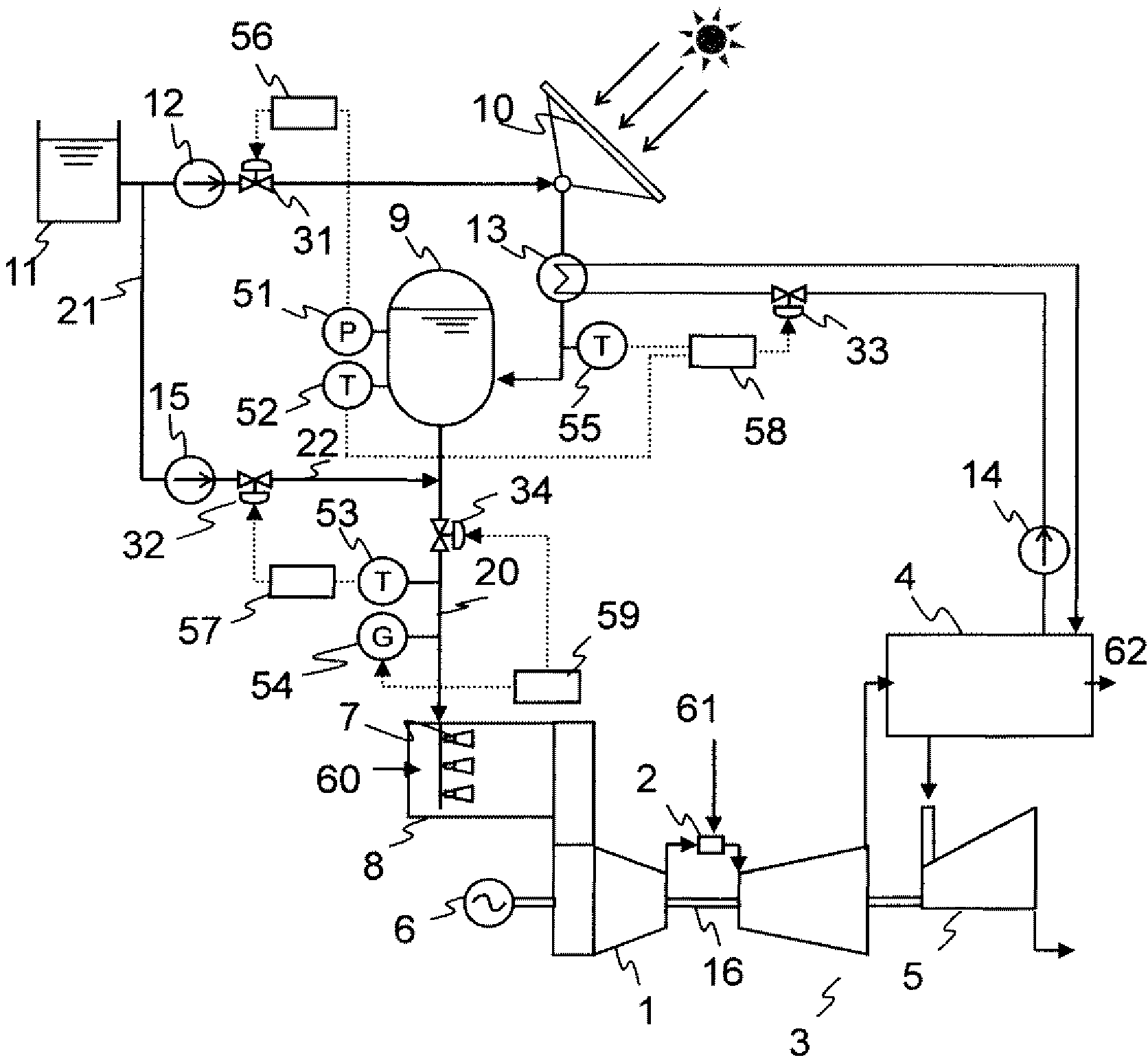
[0058] Hereinafter, a third embodiment of the solar heat utilization combined cycle power plant of the present invention will be described with reference to the drawings. image 3 It is a system configuration diagram showing the third embodiment of the solar heat utilization combined cycle power plant of the present invention. exist image 3 in, with figure 1 and figure 2 The same symbols as shown are the same parts, and therefore detailed description thereof will be omitted.

[0059] image 3 Represents the system flow of a combined cycle power plant with collectors, heat storage, spraying plant, gas turbine, heat recovery boiler, steam turbine. The third embodiment of the solar heat utilization combined cycle power plant of the present invention is composed of the same combined cycle power plant as that of the second embodiment, but differs in the following configurations.

[0060] In the second embodiment of the solar heat utilization combined cycle power plant of the...


PUM


Abstract

A combined cycle power generation plant that uses solar heat and is equipped with: a compressor (1) that pressurizes air for combustion; a combustion chamber (2) that mixes / burns the aforementioned combustion air (60) and a gas turbine fuel (61) to generate high-temperature combustion gas; a gas turbine (3) that drives the compressor (1) using the aforementioned combustion gas; an exhaust heat recovery boiler (4) that obtains steam from the heat energy of the exhaust gas from the gas turbine (3); and a steam turbine (5) that is driven using steam obtained with the exhaust heat recovery boiler (4). The power generation plant is further equipped with: a heat collector (10) that converts feed water to high-temperature water by means of the heat energy of sunlight; a heat accumulator (9) that stores high-pressure, high-temperature water obtained from the heat collector (10) and the exhaust heat recovery boiler (4); and a spraying device (4) that sprays the high-pressure, high-temperature water stored in the heat accumulator (9) into the intake air of the compressor (1) as a water spray.

Description

technical field [0001] The present invention relates to a solar heat utilization combined cycle power plant equipped with a solar heat collector for obtaining thermal energy from sunlight. Background technique [0002] As power plants that supply electric power for industrial use, there are gas turbine power plants and combined cycle power plants. It is known that when the gas turbine power plant and the combined cycle power plant are operated during a period when the atmospheric temperature rises, such as in summer, the amount of air intake by the compressor is relatively reduced compared with the case of operating during a period when the atmospheric temperature is low , power generation output and thermal efficiency decrease. [0003] Disclosed is a regenerative cycle gas turbine power plant that cools intake air by spraying fine liquid droplets upstream of a compressor in order to achieve both an increase in power generation output and an improvement in thermal efficien...

Claims


Application Information

Patent Timeline
Patent Type & Authority Applications(China)
IPC IPC(8): F02C7/143F01K23/10F02C6/18F24J2/42F24S90/00
CPCF24J2/04F02C6/18F02C3/30F22B1/1815Y02E10/46F01K23/101Y02E20/16F02C1/05F01K23/10F03G6/003F22B1/006F02C7/143F03G6/064F02C3/305F01K23/108F24S10/00F02C7/1435
Inventor 吉田泰浩片桐幸德矢敷达朗吉田卓弥高桥一雄楠见尚弘关合孝朗
Owner MITSUBISHI POWER LTD
Why Eureka
Try Eureka