
Loop-shaped heat pipe and electronic device

A technology of annular heat pipes and electronic components, applied in lighting and heating equipment, indirect heat exchangers, etc., can solve the problems of reduced cooling performance, lack of thermal insulation, pressure resistance and airtight reliability, etc., to achieve effective cooling , the effect of stable circulation

Active Publication Date: 2013-05-01
FUJITSU LTD
View PDF7 Cites 7 Cited by
  • Summary
  • Abstract
  • Description
  • Claims
  • Application Information

AI Technical Summary

Problems solved by technology

However, if the material of the evaporator housing is selected as resin, pressure resistance and long-term airtight reliability will become problems
In addition, when a metal with low thermal conductivity is used, the thermal conductivity of the metal is tens to hundreds of times that of the resin, so it does not have sufficient thermal insulation and cannot sufficiently suppress the reduction in cooling performance. And other issues

Method used


Image

  • Loop-shaped heat pipe and electronic device
  • Loop-shaped heat pipe and electronic device
  • Loop-shaped heat pipe and electronic device

Examples


Embodiment Construction

[0054] Hereinafter, embodiments will be described in detail with reference to the drawings. However, various constituent elements in the drawings are not necessarily drawn on the same scale. Also, the same or similar reference signs are used for the same or corresponding components in a plurality of drawings.

[0055] First, refer to Figure 3A — Figure 3D The evaporator 110 included in the loop heat pipe according to one embodiment will be described. Figure 3A The main components of the evaporator 110 are shown in an exploded view. Figure 3B shown from other directions in Figure 3A The shunt 140 shown in . and, Figure 3C is observed along the flow of the working fluid by Figure 3A The cross-sectional view of the evaporator 110 obtained from the constituent elements shown in Figure 3D shown in Figure 3C The BB' section. Among them, please note Figure 3C Not a cross-sectional view when cutting the evaporator with a plane.

[0056] In the illustrated example, ...


PUM


Abstract

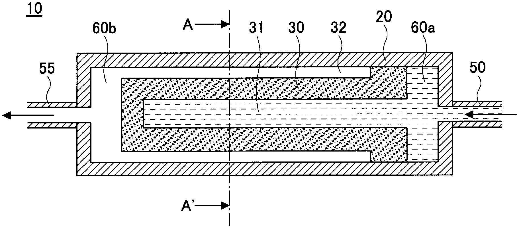
An evaporator (110) of a loop-shaped heat pipe comprises: a case (121, 122) which is provided with a fluid inlet and a steam outlet; and at least one porous body (130) which is arranged in the case and through which a liquid-phase working fluid is introduced onto the inner surface of the case. The evaporator (110) additionally comprises a liquid supply tube (140) which is arranged in the case (121, 122) and through which the working fluid is introduced from the fluid inlet to the at least one porous body (130). The liquid supply tube (140) comprises a material having a lower heat conductivity than that of a material that constitutes the case (121, 122). The vaporization of the working fluid that flows into the evaporator (110) can be prevented before the working fluid reaches the porous body (130), and therefore the steady circulation of the working fluid can be achieved.

Description

technical field [0001] The invention relates to an annular heat pipe and electronic equipment. Background technique [0002] As means for cooling various heat generators, loop heat pipes are known. The annular heat pipe has a structure in which the evaporator and the condenser are connected into a ring by using a steam pipe and a liquid pipe. The evaporator uses the heat from the heating element to vaporize the working fluid (liquid-phase working fluid), and the condenser uses the heat from the heating element to vaporize the working fluid. The vaporized working fluid (working fluid in the gas phase) is condensed by heat dissipation. The evaporator obtains heat from the heating element as the heat of vaporization of the working fluid, and also acts as a pump to drive the circulation of the working fluid. [0003] exist Figure 1A - 1C shows the structure of a typical evaporator 1 . Figure 1A is a schematic cross-sectional view of the evaporator 1 when viewed along the flo...

Claims


Application Information

Patent Timeline
Patent Type & Authority Applications(China)
IPC IPC(8): F28D15/02
CPCF28D15/0233F28D15/0266F28D15/043F28D15/046
Inventor 内田浩基
Owner FUJITSU LTD
Learn More