Method and device for determining model parameters to control modules of a steam power plant
A technology of model parameters and steam generators, which is applied in the direction of steam engine devices, steam generation, control systems, etc., which can solve the unavoidable, inaccurate estimated values of boiler time constants stored in time constants, and the inability to rule out the decline of control quality over time, etc. problems to achieve high flexibility
- Summary
- Abstract
- Description
- Claims
- Application Information
AI Technical Summary
Problems solved by technology
Method used
Image

Examples
Embodiment Construction
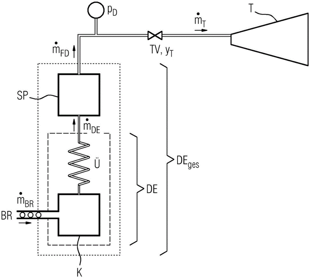
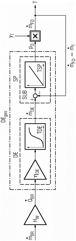
[0023] Figure 1 is used to clarify the dynamic process of steam generation and explain two model parameters: boiler time constant TDE and storage time constant TSP.
[0024] exist Figure 1A A block diagram of the steam generator is shown in simplified form in . The combustion chamber of boiler K is supplied with fuel BR at its inlet, wherein the fuel can be, for example, coal pulverized into pulverized coal in a coal pulverizer. Fuel can be measured here material flow. The corresponding thermal power of the fuel Corresponds to the material flow corrected for the heating value HW of the fuel. Fuel is burned inside the boiler K. In order to generate steam, the feed water conveyed in the pipes in the walls of the steam generator is heated and evaporated. through the superheater The piping system delivers this steam to the turbine valve TV. steam generation DE ges The overall process is ideally divided into two partial processes: the actual steam generation DE and the ...
PUM
 Abstract
Description
Claims
Application Information
PatSnap Eureka turns technology decisions into work you can execute. Powered by our Innovation Knowledge Graph, it runs expert workflows across engineering, life sciences, materials and intellectual property. Get your review-ready output in minutes.


