Hybrid HVDC converter

A converter, commutated thyristor technology, applied in the output power conversion device, the conversion of AC power input to AC power output, the conversion of AC power input to DC power output, etc., can solve the current increase, DC side voltage reduction, conversion The size, weight and cost of the device hardware are increased, so as to simplify the design, eliminate the fault current, and minimize the switching loss and electromagnetic interference.

Inactive Publication Date: 2013-05-01
ALSTOM TECH LTD
View PDF4 Cites 20 Cited by
  • Summary
  • Abstract
  • Description
  • Claims
  • Application Information

AI Technical Summary

Problems solved by technology

This results in increased size, weight and cost of the converter hardware
[0007] Furthermore, the inherent regulation effect created by the impedance of the associated transformer and AC network causes the DC side voltage to decrease and the current to increase

Method used


Image

  • Hybrid HVDC converter
  • Hybrid HVDC converter
  • Hybrid HVDC converter

Examples


Embodiment Construction

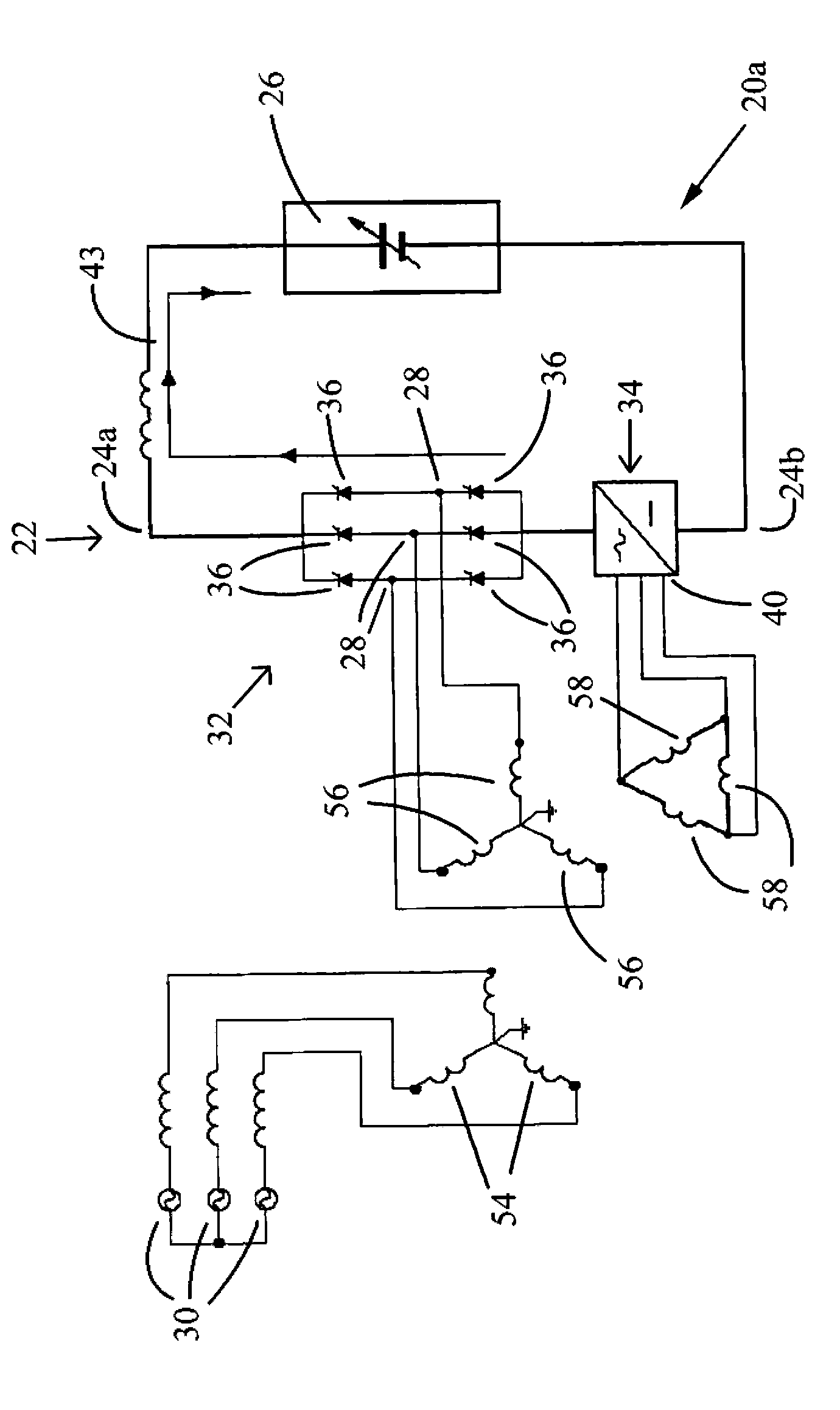
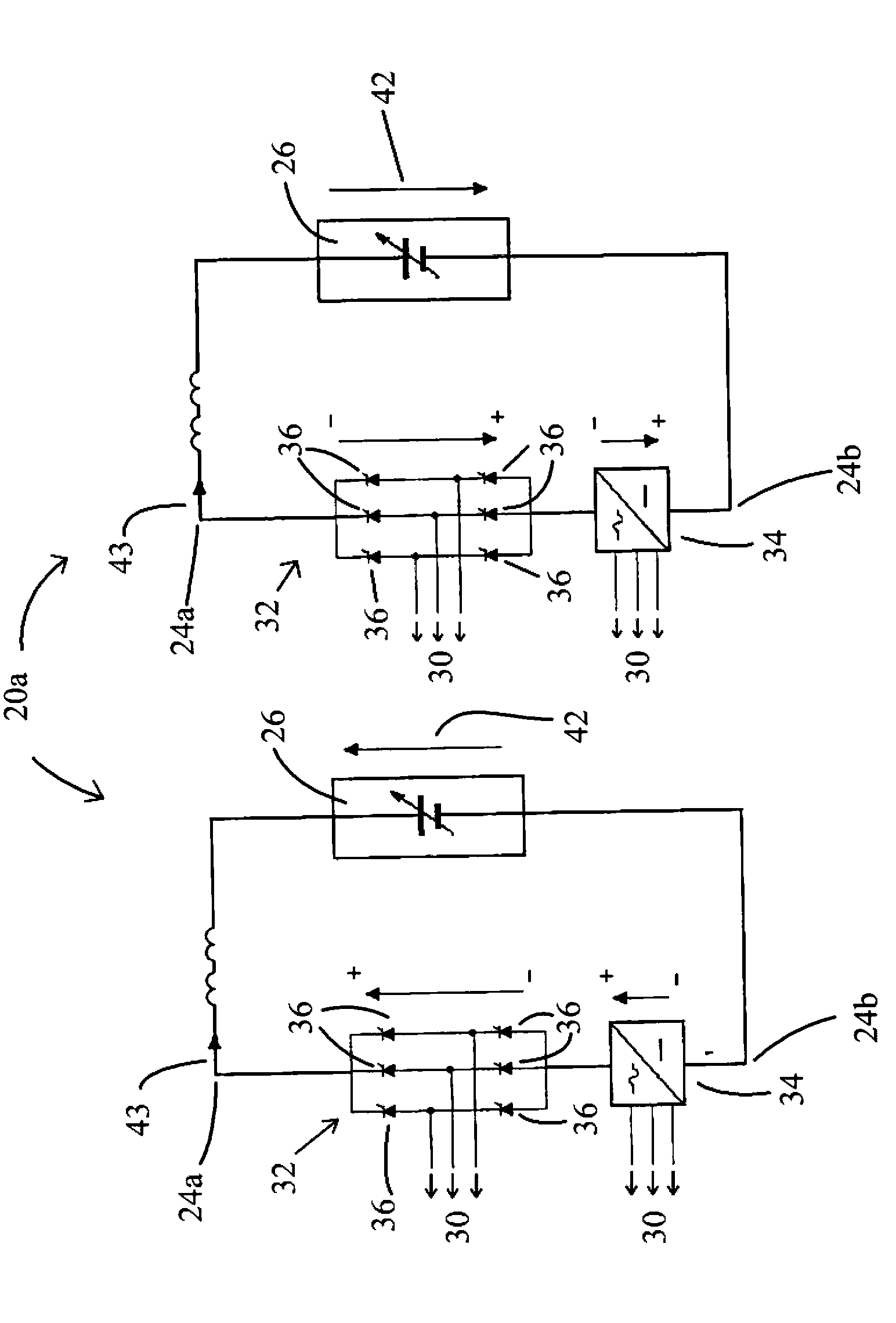
[0068] figure 1 The power electronic converter 20a according to the first embodiment of the present invention is shown.

[0069] The power electronic converter 20a includes a converter branch (limb) 22. The converter branch 22 includes a first DC terminal 24a and a second DC terminal 24b for connecting to the DC network 26 when in use, and for connecting in series when in use. Connected to the first AC terminal 28 of the AC network 30.

[0070] The converter branch 22 includes a first converter block 32 and a second converter block 34, which are connected in series between the first DC terminal 24a and the second DC terminal 24b to define a power supply for exchanging power with the three-phase AC network 30 Two-terminal DC network.

[0071] The first converter block 32 includes three wire-commutated thyristor pairs 36 connected in parallel. The midpoint among the respective wire-commutated thyristor pairs 36 defines a first AC terminal 28 for connecting to a corresponding phase in...


PUM


Abstract

The invention relates to a power electronic converter (20a) for use in high voltage direct current power transmission and reactive power compensation which comprises at least one converter limb (22) including first and second DC terminals (24a, 24b) for connection in use to a DC network (26), the or each converter limb (22) including at least one first converter block (32) and at least one second converter block (34) connected between the first and second DC terminals (24a, 24b); the or each first converter block (32) including a plurality of line-commutated thyristors (36) and at least one first AC terminal (28) for connection in use to an AC network (30), the or each second converter block (34) including at least one auxiliary converter including a plurality of self-commutated switching elements; wherein the self-commutated switching elements are controllable in use to inject a voltage to modify a DC voltage presented to the DC side of the converter limb (22) and/or modify an AC voltage and an AC current on the AC side of the power electronic converter (20a).

Description

Technical field [0001] The invention relates to a power electronic converter used in high-voltage direct current power transmission and reactive power compensation. Background technique [0002] In power transmission networks, alternating current (AC) power is typically converted to direct current (DC) power for transmission through overhead lines and / or submarine cables. This conversion eliminates the need to compensate for the AC capacitive loading effect imposed by the transmission line or cable, thereby reducing the cost per kilometer of the line and / or cable. Therefore, when long-distance power transmission is required, AC / DC conversion will bring higher cost performance. [0003] AC / DC power conversion is also used in power transmission networks that need to interconnect AC networks operating at different frequencies. [0004] In any such power transmission network, converters are needed at each interface between AC power and DC power to achieve the required conversion. Two s...

Claims


Application Information

Patent Timeline
Patent Type & Authority Applications(China)
IPC IPC(8): H02M7/757H02M7/797H02J3/36
CPCH02M1/12H02M7/797Y02E60/60H02M1/15H02J3/36H02M7/7575H02M2007/4835H02M7/4835H02M1/0085H02M1/0095H02J1/02H02M7/1626H02M7/06
Inventor 戴维·特雷纳安德烈·保乐·卡尼汉斯科林·查诺克·戴维森卡尔·戴维·巴克
Owner ALSTOM TECH LTD
Why Eureka
Try Eureka