Method for manufacturing external coating layer of optical fiber preform rod through sleeve method

An optical fiber preform and outer layer technology, applied in the field of optical fiber manufacturing, can solve the problem of wasting sleeves, etc., and achieve the effects of avoiding waste, improving geometric size, and saving production time.

Active Publication Date: 2013-05-08
FUTONG GROUP CO LTD +1
View PDF5 Cites 26 Cited by
  • Summary
  • Abstract
  • Description
  • Claims
  • Application Information

AI Technical Summary

Problems solved by technology

[0005] The technical problem to be solved and the technical task proposed by the present invention are to overcome defects such as wasted sleeves in the outer cladding of optical fiber preforms produced by the existing sleeve method, and provide a method for manufacturing optical fiber preforms by the sleeve method that can make full use of the sleeves. layer method

Method used


Image

  • Method for manufacturing external coating layer of optical fiber preform rod through sleeve method
  • Method for manufacturing external coating layer of optical fiber preform rod through sleeve method
  • Method for manufacturing external coating layer of optical fiber preform rod through sleeve method

Examples


Embodiment 1

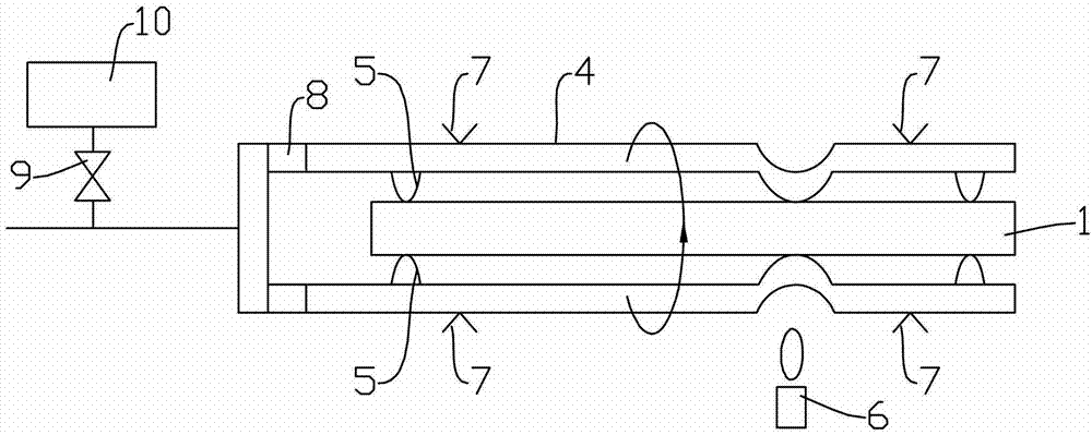
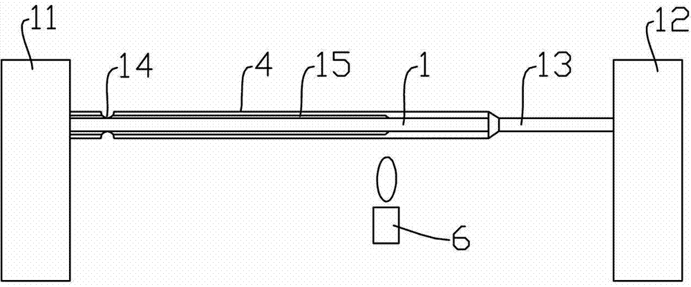
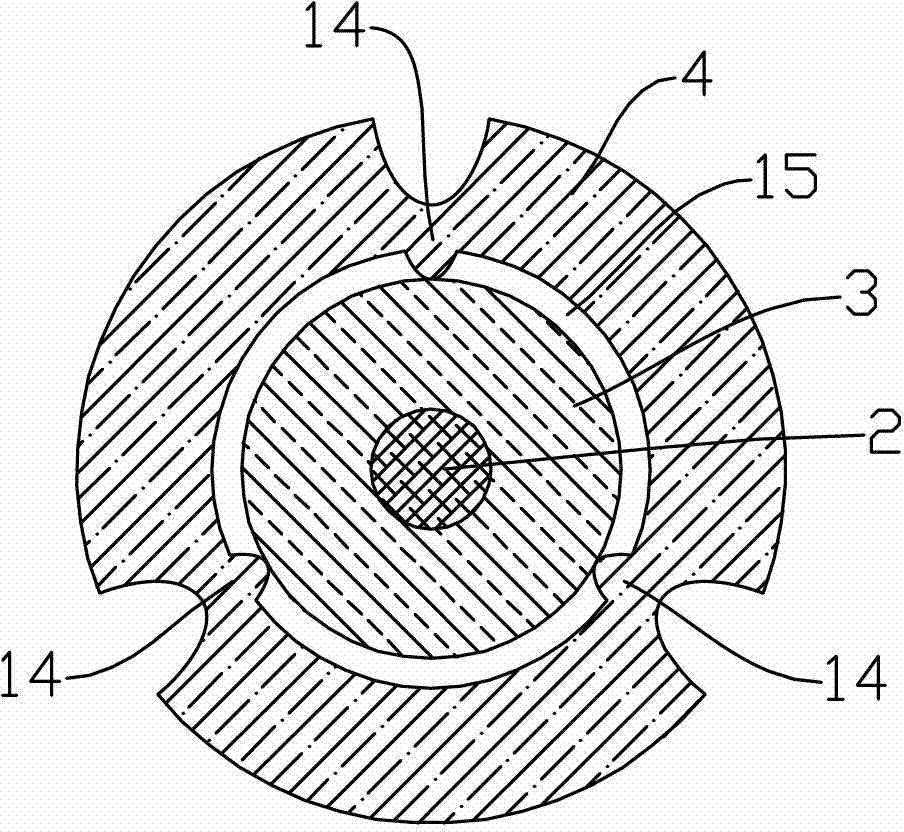
[0034] The mandrel 1 with an outer diameter of 20 mm and a length of 1000 mm is manufactured by a modified chemical vapor deposition method. Then the manufactured mandrel 1 is welded to the auxiliary glass rod 13, and an outer diameter thickened part 19 is arranged at the welding place, and the maximum outer diameter of the outer diameter thickened part 19 is 24mm. The mandrel 1 is flame polished to eliminate surface impurities. The outer diameter of the sleeve pipe 4 processed by pickling is 30mm, the inner diameter is 24mm, and the length is 1000mm. One end is welded to the handle pipe 18, and the handle pipe 18 is installed on the head chuck 71 and connected to the vacuum pump through a rotary joint. The auxiliary glass rod 13 is mounted on the tailstock chuck 72 of the lathe. Then, the whole mandrel 1 is concentrically inserted into the casing 4 until the thickened portion seals one end of the casing, and the gap 15 between the inner wall of the casing 4 and the outer dia...

Embodiment 2

[0036] The mandrel 1 with an outer diameter of 25 mm and a length of 1200 mm is manufactured by plasma chemical vapor deposition. The outer diameter of the sleeve pipe 4 processed by pickling is 32mm, the inner diameter is 27mm, and the length is 1200mm. One end is welded to the handle pipe 18, and the handle pipe is installed on the head chuck and connected to the vacuum pump through a rotary joint. Then the manufactured mandrel 1 is welded to the auxiliary glass rod 13, and an outer diameter thickened part 19 is arranged at the welding place, and the maximum outer diameter of the outer diameter thickened part 19 is 30mm. The auxiliary glass rod 13 is installed on the tailstock chuck 72 of the lathe, and the core rod 1 is flame polished to eliminate surface impurities. Then, the whole mandrel 1 is concentrically inserted into the sleeve 4 until the thickened portion seals one end of the sleeve, and the gap 15 between the inner wall of the sleeve 4 and the outer diameter of th...


PUM

PropertyMeasurementUnit
diameteraaaaaaaaaa
lengthaaaaaaaaaa

Abstract

The invention discloses a method for manufacturing an external coating layer of an optical fiber preform rod through a sleeve method, belongs to an optical fiber manufacturing technology and aims to overcome the defects of sleeve waste and the like in the manufacturing of an external coating layer of an optical fiber preform rod through a sleeve method in the prior art. In the invention, a core rod is welded onto an auxiliary glass rod, an external diameter enlarged part is arranged at the welding position, and the whole core rod is concentrically inserted into a sleeve, thus forming an annular space between the external surface of the core rod and the internal surface of the sleeve; the circumference of the sleeve is provided with at least three recess parts for fixing the core rod; a blowtorch is used to heat the external diameter enlarged part which seals the sleeve and the core rod, and negative pressure is applied to the annular space; and the blowtorch is moved to heat the sleeve and the core rod, so that the sleeve can collapse onto the core rod to form a solid optical fiber preform rod. According to the invention, the sleeve utilization rate is high; the existing improved chemical vapor deposition equipment can be fully utilized, no additional equipment investment is required, the production cost can be lowered, and the production time can be saved; and the optical fiber preform rod manufactured by the method has favorable physical dimension.

Description

technical field [0001] The invention relates to optical fiber manufacturing technology, in particular to a method for manufacturing the outer cladding of optical fiber prefabricated rods by using the casing method on improved chemical vapor deposition equipment. Background technique [0002] Optical fiber preform is the raw material for manufacturing optical fiber. In order to ensure the high purity of the preform and the low loss of the drawn optical fiber, the preform in the field of optical communication is currently manufactured by vapor deposition. For the most widely used G.652 single-mode fiber at present, almost all the optical power is transmitted in the core layer and the inner cladding layer, so the core layer and the inner cladding layer of the prefabricated rod (the core layer and the inner cladding layer together are called the core rod) The manufacture of the preform determines the optical performance of the drawn optical fiber, and the outer cladding of the ...

Claims


Application Information

Patent Timeline
Patent Type & Authority Applications(China)
IPC IPC(8): C03B37/014
CPCC03B37/01248C03B37/01211Y02P40/57
Inventor 冯高峰葛锡良杨军勇章海峰马静
Owner FUTONG GROUP CO LTD
Why Eureka
Try Eureka